- The input signals which may be set depend on the selection made at item 3 as follows.
The numbers ranging from 00 to 15 in front of the characters are registration numbers.
- For more information on output conditions see the PC Function in Chapter 10.
Continued on the following page
Continued from the previous page: GRAY&EDGE, GRAV.
Return to the MAIN OPS MENU
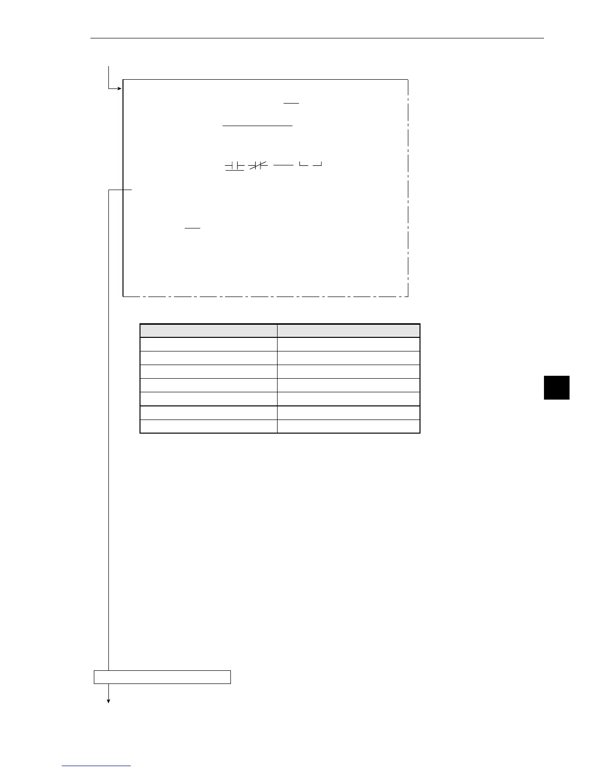
[OUTPUT CONDITIONS]
(TYPE00-MEAS.0-DST&ANGL MEAS)
1PAGE NO. 0(0~4) REG.NO YES
2SET POSITION
MOVE
3INPUT SIGNAL
MATCH M00(0~15) AGL B00(0~15)
ST-PT S00(0~15) AUX.H00(0~15)
DST.D00(0~15)
CAL.N00(0~15) AUXRLY C000(0~127)
4LOGICAL SYMBOL
5OUTPUT SIGNAL AUX.RLYC000(0~127) DEL.
6UPPER MENU
[PAGE0]
INPUT0
LOGIC
INPUT1
LOGIC
INPUT2
LOGIC
INPUT3
LOGIC
10 234567OUT
DEL.
Selection of 3
Degree of match M
Angle B
Starting point S
Auxiliary point H
Distance D
Calculation N
Secondary relay C
Input signals
00M to 15M
00B to 15B
00S to 15S
00H to 15H
00D to 15D
N00 to N15
C000 to C127