10-7
PC Function
10
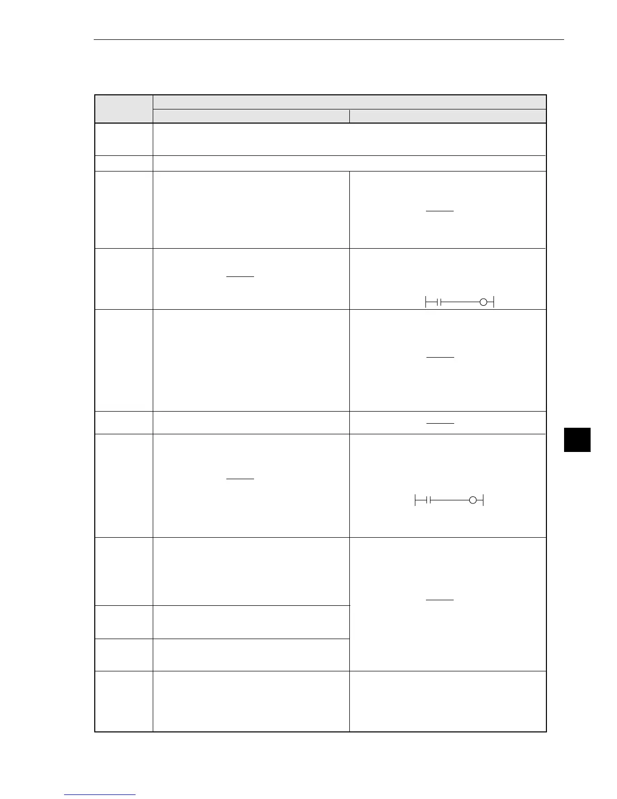
[Auxiliary relay C000 to C127]
The functions of the auxiliary relays (C000 to C127), which can be used for input and output signals,
are explained below.
C000 to C109
(internal
calculation)
Relay No.
(relay name)
Function
Use for input signals
Use for output signals
C112 (Final
evaluation
result)
C110, C111
· Relays for internal calculation
· For the final output conditions, relays also used for output in the measurement
processing cycle can be used.
· Turned ON when all of the evaluation items have
been judged OK, and turned OFF if any single item
has been judged NG.
· If C116 is not used, OK/NG will be displayed on the
MAIN OPS MENU which correspons to ON/OFF of
C112. *
· If an error occurs (C118 is turned ON),C112 will be
turned OFF (NG).
C113
(Continuous
measurement
start input)
· When C113 is ON, continuous measurements will
be executed.
(Ex) When X0 is ON,continuous measurements
will be executed.
C114
(CCD trigger
status output)
Output the CCD trigger status to C114, regardless of
the Yes/No setting for the start of the measurement.
· When “binary conversion” is specified, if the white
area is 50% or more of the image, C114 will be
turned ON, and if it is less than 50 %, C114 will be
turned OFF.
· When the “average light level” is specified, C114
will be turned ON when the image is within the
specified level range, and turned OFF when it is out
of the range.
C117
(Illuminance
monitor error)
C120 to C127
(counter reset)
· Turned OFF when the illumination exceeds the
upper or lower warning level of the illuminance
monitor set on the [MONITOR LIGHT LVL] menu
(page 9·115). Warning light levels can be set for
each of the cameras 1 and 2 separately. This relay
is turned OFF when either one of them exceeds the
upper or lower level.
C115
· The same signal as the BUSY/READY signal is
output internally.
C118
(measurement
operation error)
· Turned ON when a measurement processing error
occurs.(However, except the end code
34/35/36/3E.
- See page 15・4.)
Reserved area (Do not use these relays.)
C119
(measurement
termination)
· Turned ON upon termination of measurement
processing, and turned OFF when a measurement
start input signal is given.
· Do not use these relays for input signals.
· They are turned ON to reset counters CN0 to CN7.
C120 to C127 correspond to CN0 to CN7. Create a
circuit for sending an output signal to one of these
relays on the row following a row that contains a
counter instruction. (Counter instruction ⇒ See
page 10·12.)
X0 C113
C116
(programmable
output)
· If an output signal is passed to C116, the display of
the OK/NG result on the MAIN OPS MENU will
depend on the ON/OFF state of C116.
(Ex.)“OK” is displayed on the MAIN OPS MENU
when C000 is ON, and “NG” when the C000 is
OFF.
· If C116 relay is not used, the display of the OK/NG
result will depend on of the final evaluation result
(C112).*
C000 C116
* OK/NG displayed on the MAIN OPS MENU
-
See page 7·2.)