10-8
PC Function
10
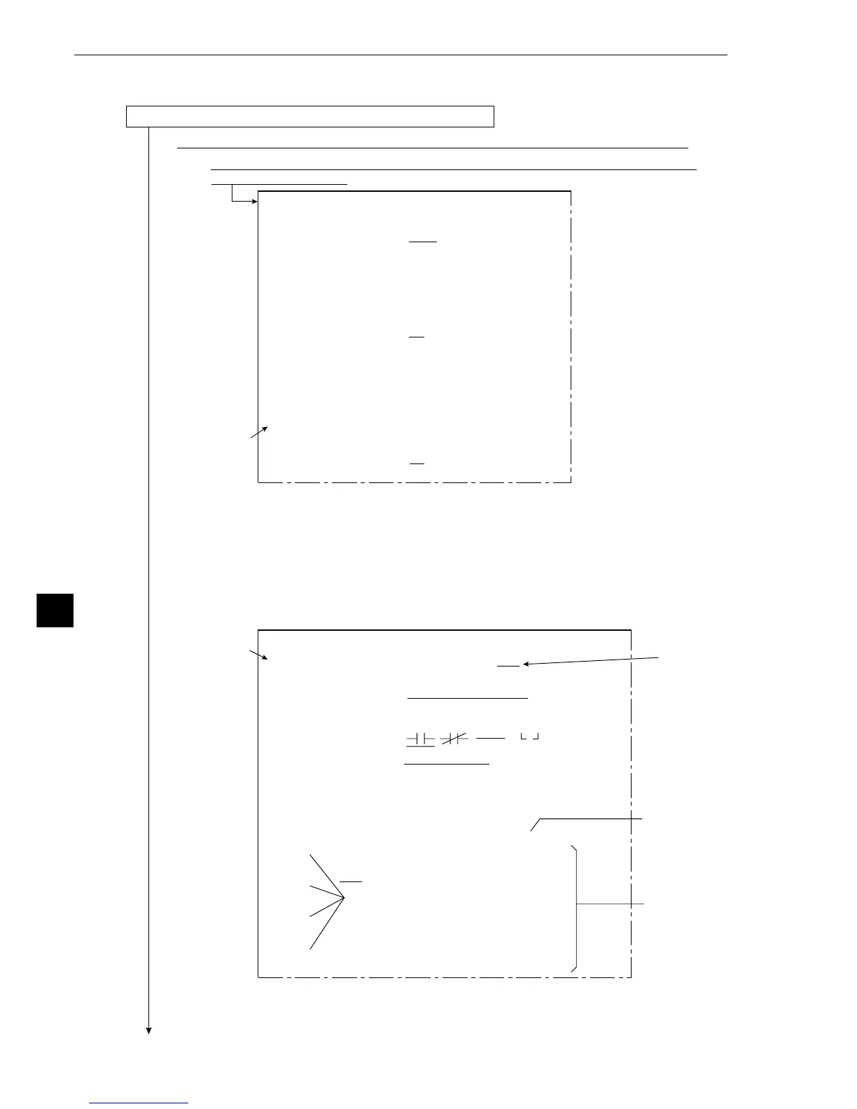
[2] Procedure for creating the final output conditions in a ladder circuit
A ladder circuit can be created for each object type (0 to 15) using the following procedure.
(1) Operation to invoke the [FINAL OUTPUT COND.] menu
1. Move the cursor to item r FINAL OUTPUT COND with the up and down keys, and press the
SET key.
- The [RESULTS OUTPUT] menu will be displayed.
2. After moving the cursor to item 1 PAGE NO. (register number) with the up and down keys,
and pressing the SET key, specify page number "0" with the up and down keys, set the REG.
(register) item to YES with the left and right keys, and press the SET key. - Items 2 to 5
will be displayed.
Continued on the following page
1
[OBJECT TYPE COND]
1OBJECT TYPE NO.
00(0~15)
2EDIT
COPY(←OBJTYPE00) INITIALIZE
3TITLE REGISTRATION
(TO NEXT SUB-MENU)
4MEAS.0, CAMERA1
NO (TO NEXT SUB-MENU)
5POS. ADJ.CAMERA1 NO ADJ. [
REG. 0-1PNTSXY]
6MEAS.0, CAMERA2
NO (TO NEXT SUB-MENU)
7POS. ADJ.CAMERA2 NO ADJ. [
REG. 0-1PNTSXY]
8SELECT CAMERA IMG
NO CAM1 CAM1 CAM1&2
0MEASUREMENT 1
NO (TO NEXT SUB-MENU)
qMEASUREMENT 2
NO (TO NEXT SUB-MENU)
wMEASUREMENT 3
NO (TO NEXT SUB-MENU)
eFINAL CALC RESULT
(TO NEXT SUB-MENU)
rFINAL OUTPUT COND
(TO NEXT SUB-MENU)
tSYSTEM-IN/OUT
(TO NEXT SUB-MENU)
yHALT MEAS ON NG
NO YES
uUPPE
R MENU
On the MAIN OPS MENU, move the cursor to SET-SCRN item, and press the SET key.
-On the [SYSTEM SETUP] menu, move the cursor to item 2 OBJECT TYPE COND
and press the SET key.
2
2
[RESULTS OUTPUT]
(TYPE00)
1PAGE.NO. (0~7) REG.NO YES
2SET POSITION MOVE
3INPUT SIGNAL AUXRLY C112(0~127) EXT-INP X0(0~6)
TMR TM0(0~7) CNT CN0(0~7)
AN00(0~15) OUT Y00(0~15)
4LOGICAL SYMBOL
5OUTPUT SIGNAL OUT Y00(0~15) AUXRLY C000(0~127)
TMR TM0(0~7) SET-VL000(000~999)
CNT CN0(0~7) SET-VL000(000~999)
DEL.
6UPPER MENU
[PAGE0]
INPUT0
LOGIC
INPUT1
LOGIC
INPUT2
LOGIC
INPUT3
LOGIC
10 234567OUT
DEL.
Row No.
Column No.
Ladder circuit
display area