10-10
PC Function
10
Final calcu-
lation result
terminals
AN0 to
AN15
When the final numerical calculation results AN0 to AN15 are OK,
these terminals are turned ON. If any of the results are NG, they
are turned OFF.
(See item 9-2 [4] for details about the final numerical calculation.)
Kind of
input signal
External input
terminals
Timer
terminals
Counter
terminals
TM0 to TM7
CN0 toCN7
Function
Data
memory No.
X0 to X6
The external input terminals X0 to X6 can be assigned.
Output
terminals
Y0toY15
They can be used as auxiliary relays for the external output
terminals Y0 to Y15.
When any of the timer instructions TM0 to TM7 causes a time-out,
the corresponding terminal is turned ON. When a timer instruction
input is switched OFF, the terminal is turned OFF.
When any of the counter instructions CN0 to CN7 counts out, the
corresponding terminal is turned ON. When any of the counter
reset relays C120 to C127 for the respective counters is turned
ON, the corresponding terminal is turned OFF.
· See page 10-7 for details about the auxiliary relays C000 to C127.
3. Move the cursor to item 4 LOGICAL SYMBOL with the up and down keys, and press the SET
key.
4. Move the cursor to the logic symbol to be used for the input signal selected in step 3, and
press the SET key.
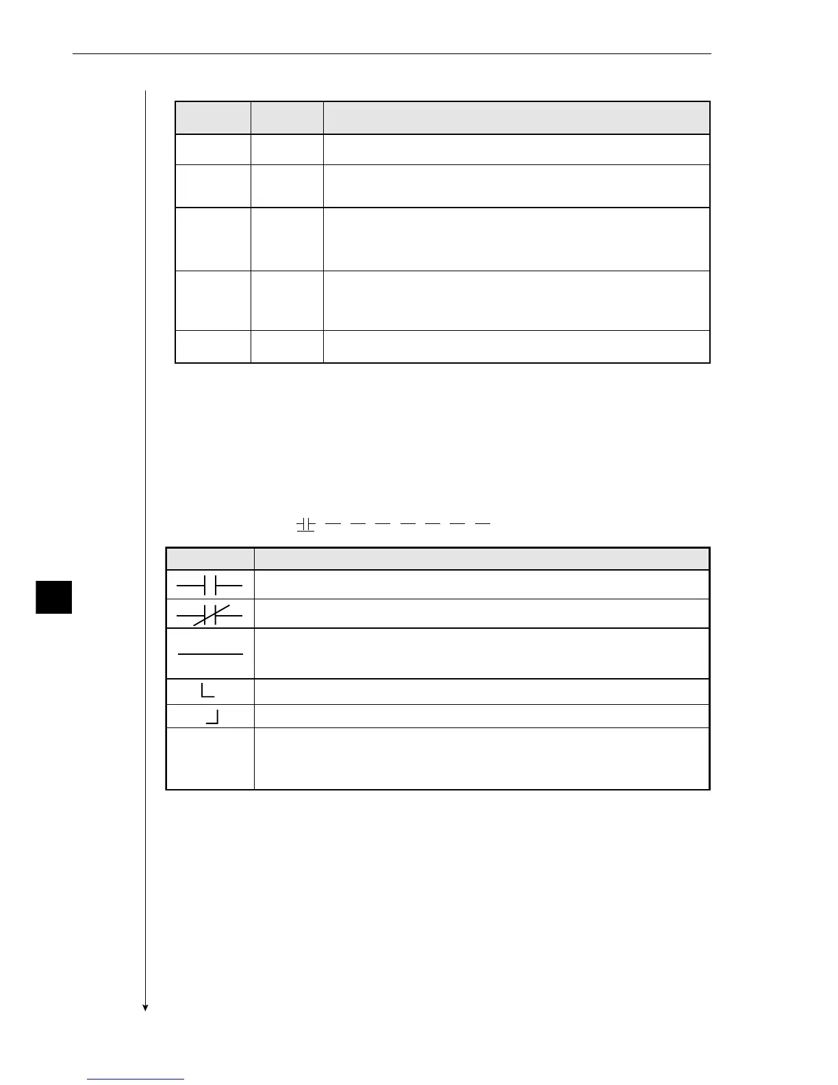
- The logic symbols and the input signals will be displayed as a ladder circuit.
Display example:
Deletes the contact on the cursor.
(Contacts after the deleted contact will not be brought forward.)
Note: This symbol cannot be used on the first row.
Deletes the contact on the cursor.
(Contacts after the deleted contact will be brought forward.)
When a contact exists only on the first row, if the contact is deleted, also the
output relay will also be deleted.
Used to create an OR circuit.
Used to create an OR circuit
Deletion
Logic symbol Function
a contact on a series circuit (ON, when the evaluation result is OK)
b contact on a series circuit (OFF, when the evaluation result is OK)
C000
01234567OUT
[PAGE0]
INPUT0
LOGIC
Continued on the following page
From the preceding page