11-7
11
Setting the Input/Output Conditions
(4) Measurement start input = general-purpose serial, object type change = general-purpose
serial, result output = general-purpose serial/parallel
[I/O SETTINGS]
1 MEASTRIGINPI/F
PARALLEL SERIAL CCD-TRIG
8
SERIAL CONDITIONS
(TO NEXT SUB-MENU)
· Setting order
1
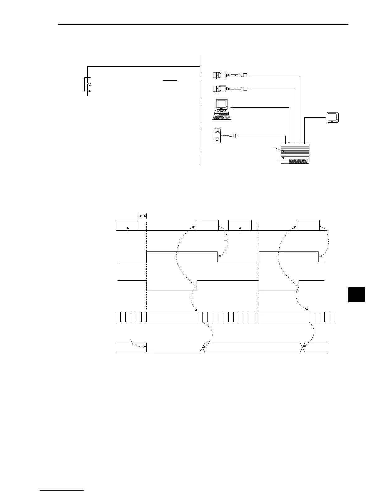
→8 · Configuration example
IV-S20 main housing
Power supply (24 VDC)
Monitor
Remote key pad
Personal computer
Command, response
Camera 1 (image capturing)
Camera 2 (image capturing)
- See pages 13-6 and 13-7 for details about the measurement execution commands (codes
10, 11, 12 and 13
(H)
).
- Time chart
P
C
P
C
P
C
P
C
P
C
P
C
P
C
P
C
P
C
P
C
P
C
P
C
P
C
P
C
P
C
P
C
P
C
P
C
P
C
P
C
P
C
P
C
P
C
Result output Result output
Result
output
Result
output
5 ms
or less
BUSY output
Measurement result is
valid at the end of a
measurement
PC calculation
condition
Terminate
measurement
(C119)
Halt PC operation
during measurement
Halt PC operation
during measurement
When the object type is changed,
all Y output and auxiliary relays turn OFF.
Parallel output is valid for PC
control after the measurement
result is determined.
Parallel output
(Y0 to Y7)
Serial
Mesurement
trigger
command
Mesurement
trigger
command
BUSY signal is
turned OFF at the
conclusion of the
result output.