11-8
11
Setting the Input/Output Conditions
[
I/O SETTINGS
]
1
MEAS TRIG INP I/F PARALLEL SERIAL CCD-TRIG
2
START CCD SAMPLE
AUTO(EDGE LEVL) PARALEL SERIAL
3SERIALOUTPUTNOPC-LINKSERIAL
(CCD SAMPLING=PARALLEL)
Settings listed in Section 11-3 “CCD trigger”
Start sampling input
X0
(photo sensor or
proximity sensor)
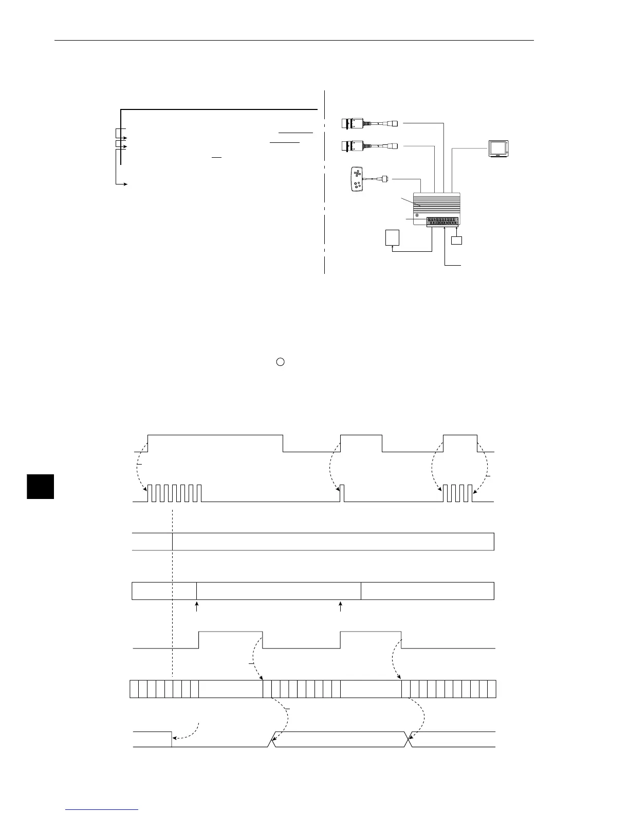
· Setting order 1 →2(→3) · Configuration example
Type selection switch
(X1 to X4)
IV-S20 main
housing
Power supply
(24 VDC)
Monitor
Camera 1 (image capturing + CCD trigger)
Camera 2 (image capturing)
Remote keypad
External output
(Y0 to Y7)
Warning lamp
(5) Measurement start input = CCD trigger, start sampling = parallel, object type change =
parallel, result output = parallel
Note 1: When the settings listed in section 11-3 "CCD trigger" have not been made, a CCD
TRIGGER NOT SET. (error 34) will occur.
Note 2: Start sampling input (X0)
1. Sampling will be performed while this terminal is ON. When it is turned OFF, the
sampling will stop.
During sampling, will flash in the upper right corner of the MAIN OPS MENU.
2. After the measurement is terminated, the sampling will be restarted when the
X0 terminal is changed from OFF to ON.
· Time chart
P
C
P
C
P
C
P
C
P
C
P
C
P
C
P
C
P
C
P
C
P
C
P
C
P
C
P
C
P
C
P
C
P
C
P
C
P
C
P
C
P
C
P
C
P
C
P
C
P
C
P
C
P
C
P
C
Result output Result output
Measurement
start input
(X0)
CCD trigger
cycle
Start accd sampling by turning ON
measurement start input (X0).
Start accd sampling
by turning OFF
measurement start
input (X0).
CCD trigger
window
(not highlighted)
Object type
number input
(X1 to X4)
Specified object type number
Black White
Trigger Trigger
Black
BUSY output
Measurement result
is valid at the end
of a measurement
PC calculation
condition
Halt PC operation
during measurement
Halt PC operation
during measurement
When the object type is changed,
all Y output and auxiliary relays
turn OFF.
Parallel output is valid for PC
control after the measurement
result is determined.
Parallel output
(Y0 to Y7)