11-15
11
Setting the Input/Output Conditions
[I/O SETTINGS]
1
MEAS TRIG INP I/F PARALLEL SERIAL CCD-TRIG
2
START CCD SAMPLE
AUTO (EDGE LEVL) PARALEL SERIAL
3OUTPUTOBJ.TYPE
PARALLEL SERIAL
(CCD SAMPLING=AUTOMATIC)
8
SERIAL CONDITIONS
(TO NEXT SUB-MENU)
Measurement is started when the CCD trigger level is ON.
Measurement is started when a CCD trigger signal is received.
Select one of
the following.
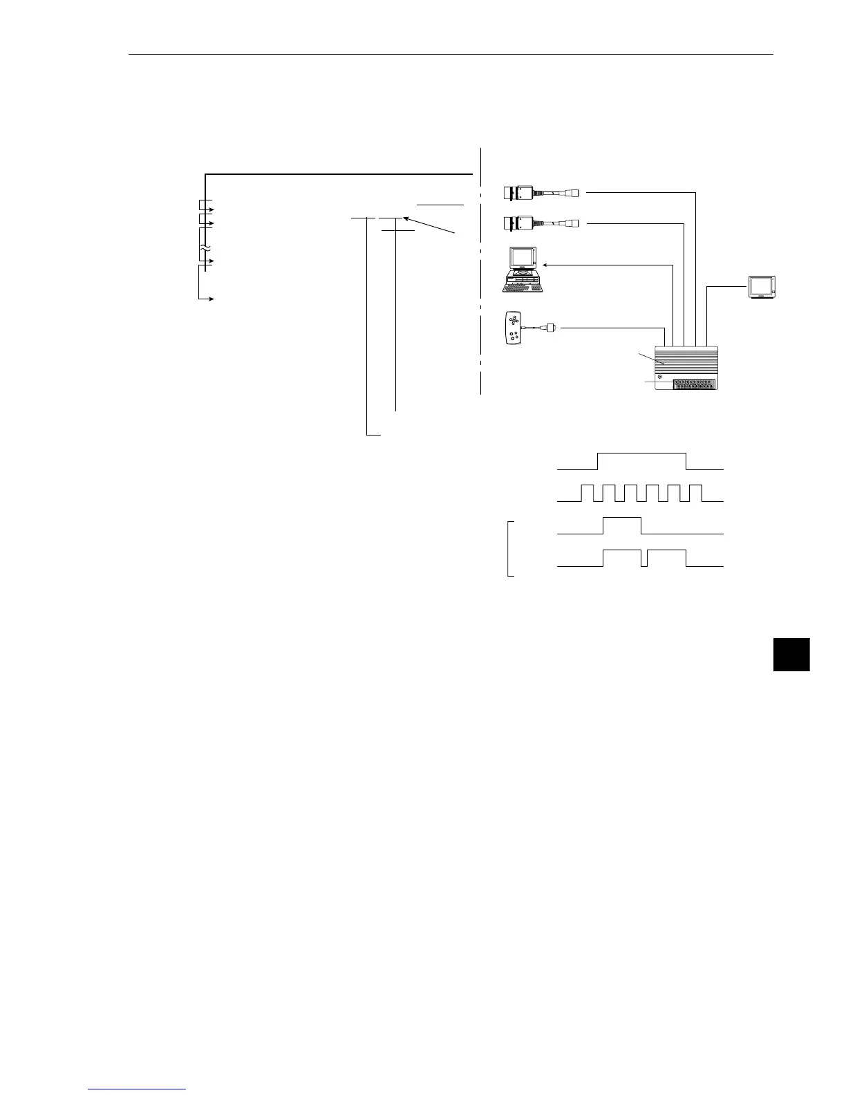
· Configuration example
IV-S20 main housing
Power supply (24 VDC)
Monitor
Camera 1 (image capturing + CCD trigger)
Camera 2 (image capturing)
Remote key pad
Data
Settings listed in section
11-3 “CCD trigger”
· Setting order 1 →2→
3
→8
CCD trigger
Work
Black White
Edge
Level
Measurement
Personal computer
(10) Measurement start input = CCD trigger, start sampling = auto, object type change =
general purpose serial, result output = general purpose serial/parallel
The general purpose serial command (code 55
(H)
) is used to change the object type.