11-16
11
Setting the Input/Output Conditions
Note: Result output; The data in the block No., set in item 5 COMPUTER LINK OUT
&SERIAL OUTPUT on the [OBJECT TYPE I/O] menu, will be transmitted to the
personal computer. (See page 11-20.)
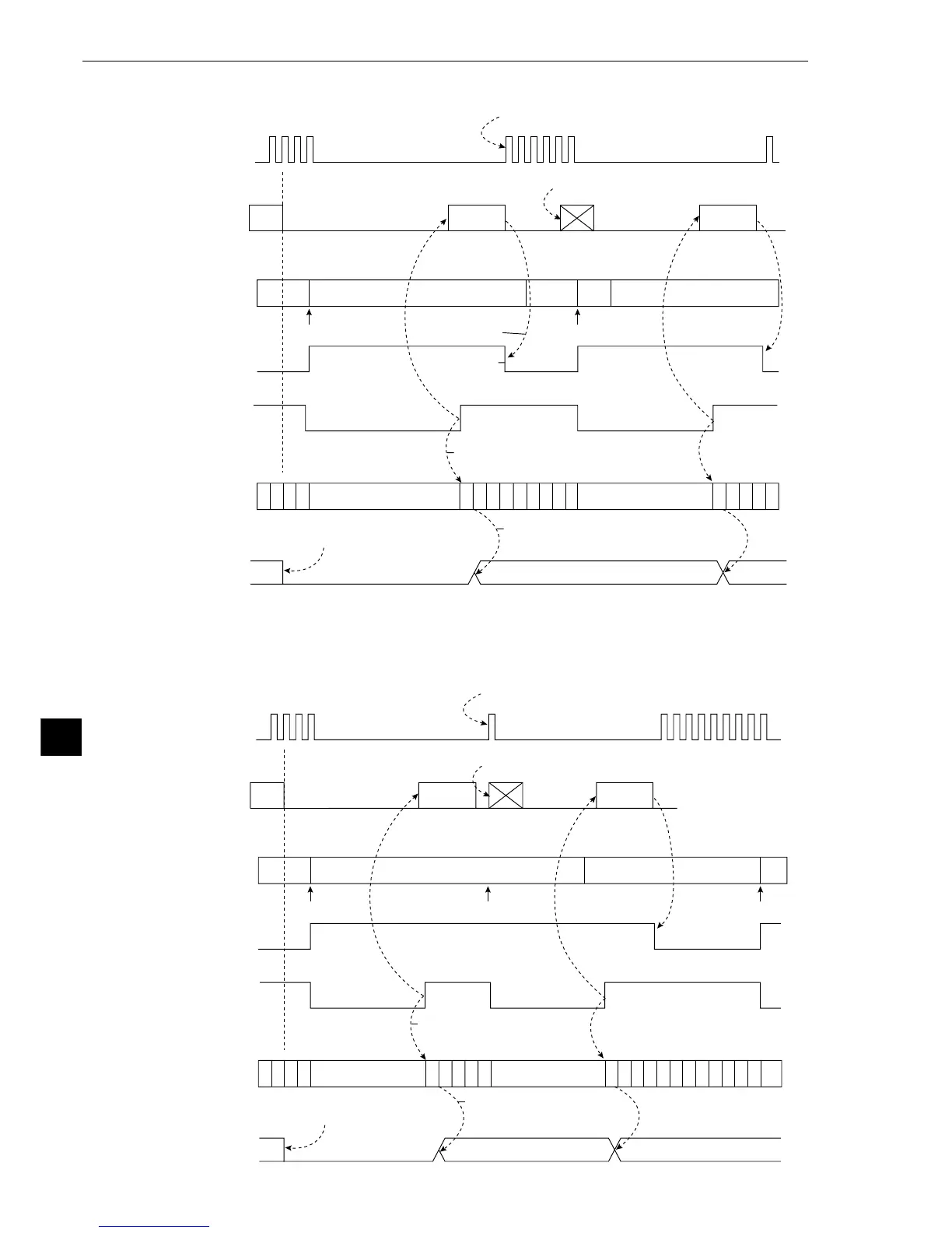
- Time chart (when auto mode (edge) is selected for as the CCD sampling start)
P
C
P
C
P
C
P
C
P
C
P
C
P
C
P
C
P
C
P
C
P
C
P
C
P
C
P
C
P
C
P
C
P
C
P
C
Result
output
Result
output
Result output Result output
CCD trigger
cycle
Serial
CCD trigger
window
(not highlighted)
Restarts CCD sampling automatically after
measurement is completed.
White White
Trigger Trigger
Black
Type Type
Black Black
BUSY output
Terminate
measurement
(C119)
Measurement result is valid at the end of
a measurement
PC calculation
condition
Parallel output
(Y0 to Y7)
Halt PC operation
during measurement
Halt PC operation
during measurement
When the object type is changed,
all Y output and auxiliary relays turn OFF.
Parallel output is valid for PC control after
the measurement result is determined.
When a trigger signal is input during
sending object type change command,
this command will be invalid.
Turn OFF
BUSY signal by
termination of result
output.
P
C
P
C
P
C
P
C
P
C
P
C
P
C
P
C
P
C
P
C
P
C
P
C
P
C
P
C
P
C
P
C
P
C
P
C
P
C
P
C
P
C
Result
output
Result
output
Result output Result output
CCD trigger
cycle
Serial
CCD trigger
window
(not highlighted)
Restarts CCD sampling automaticallyafter
measurement is completed.
White
Whi-
te
Trigger Trigger
Type Type
Trigger
Black Black
BUSY output
Terminate
measurement
(C119)
Measurement result is valid
at the end of a measurement
PC calculation
condition
Parallel output
(Y0 to Y7)
Halt PC operation
during measurement
Halt PC operation
during measurement
When the object type is changed,
all Y output and auxiliary relays
turn OFF.
Parallel output is valid for
PC control after the
measurement result is
determined.
When a trigger signal is input during
sending object type change command,
this command will be invalid.
- Time chart (when auto mode (level) is selected for as the CCD sampling start)