OPERATING INSTRUCTIONS | Bulkscan LMS511 8014829/ZNC5/2017-06-06 | SICK
Subject to change without notice
30
MOUNTING
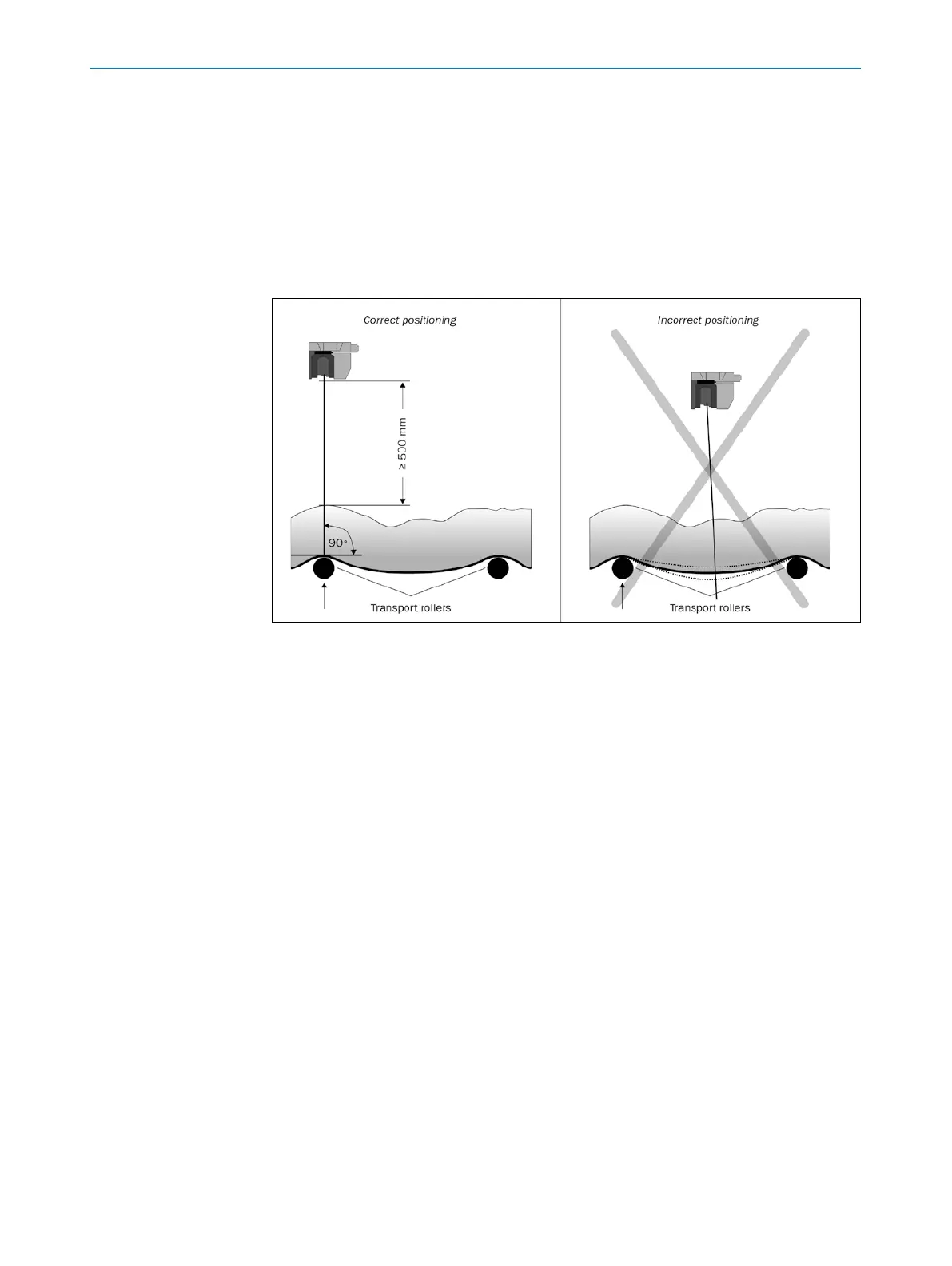
The sensor is to be attached in the center over the conveyor belt on mounting ¬brack-
ets to be installed on site. During this process the following conditions must be met to
ensure measurement accuracy:
• Optical axis over a transport roller
• Minimum distance to the top edge of the bulk: 500 mm
• Perpendicular alignment to the direction of transport.
Fig. 9: Positioning of the sensor above the conveyor belt
Theeldofviewofthesensormustbeclear.
5.3 Mounting the sensor
• PayattentiontothemaximumtorquefortheBulkscanxingscrews:
◦ M6 rear = max. 12 Nm
◦ M8 side = max. 16 Nm
• Regularlycheckthetightnessofthexingscrews.
• Onsystemsthatsufferfromheavyvibration,preventthexing¬screws¬fromcom-
ing loose using screw locking devices.
Possible ways of mounting the Bulkscan:
• Direct mounting (see "5.3.1 Direct mounting“ on page 31).
• Mounting with mounting kit 1 (see "5.3.2 Mounting with mounting kit 1“ on page
31).
• Mounting with mounting kit 2 (see "5.3.3 Mounting with mounting kit 2“ on page
32). (Only in conjunction with mounting kit 1).
• Mounting with mounting kit 3 (see "5.3.4 Mounting with mounting kit 3“ on page
33). (Only in conjunction with mounting kit 1 and 2).
• Mounting with mounting bracket on existing mounting kit LMS2xx
(see "5.3.5 Mounting with mounting bracket on existing mounting kit LMS2xx“ on
page 34).
• Mounting with mounting bracket and mast bracket (see "5.3.6 Mounting with mount-
ing bracket and mast bracket“ on page 35).
Note