OPERATING INSTRUCTIONS| Bulkscan LMS5118014829/ZNC5/2017-06-06| SICK
Subject to change without notice
47
ELECTRICAL INSTALLATION
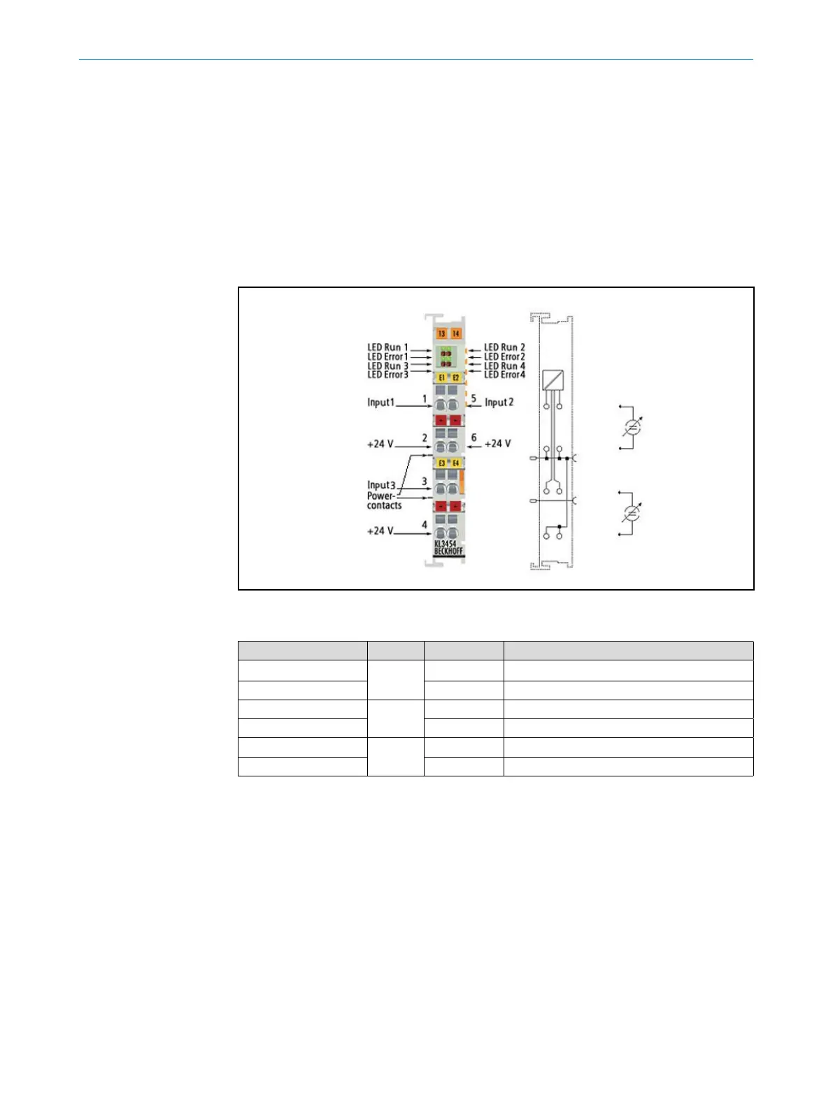
6.3.6.4 Analog input terminal KL3454
The KL3454 analog input terminal process signals in the range between 4 and 20 mA.
The current is digitized to a resolution of 12 bits, and is transmitted, in an electrically
isolated form, to the higher-level automation device. In the KL3454 Bus Terminal, the
four inputs are 2-wire versions and have a common ground potential. This reference
ground for all inputs is connected to the 0 V power contact. The 24 V power contact is
connected to the terminals, in order to enable the connection of 2-wire sensors without
external supply. The power contacts are connected through. Overload is detected and
the terminal status is relayed to the controller via the K-bus. The Run-LEDs indicate the
data exchange with the Bus Coupler, the Error-LEDs indicate overload or wire breakage.
Fig. 30: KL3454 - Connection
Terminal point nr. Channel Name Connection for
1 1 Input 1 Analog input 1, belt speed (4...20 mA)
2 +24 V Analog input 1, 24 V
3 3 Input 3 Analog input 3, bulk density (4...20 mA)
4 +24 V Analog input 3, 24 V
5 2 Input 2 Analoginput2,massowrate(4...20mA)
6 +24 V Analog input 2, 24 V