OPERATING INSTRUCTIONS| Bulkscan LMS5118014829/ZNC5/2017-06-06| SICK
Subject to change without notice
39
ELECTRICAL INSTALLATION
6.2.1 Supply voltage connection
4
2
3
5
1
Fig. 17: Pin assignment of the "Power" connection (M12×5 plug, A coded)
Pin Wire color Signal Function
1 Brown 24 V SYS Power supply sensor
2 White 24 V HEAT Power supply heater
3 Blue GND SYS Ground power supply sensor
4 – Reserved Do not use
5 Black GND HEAT Ground power supply heater
Tab. 5: Pin assignment of the "Power" connection
Pre-assembledconnectioncableswithyingleadsareavailableasaccessories(see
"12.2 Accessories“ on page 77).
Other connection cables may have different wire colors.
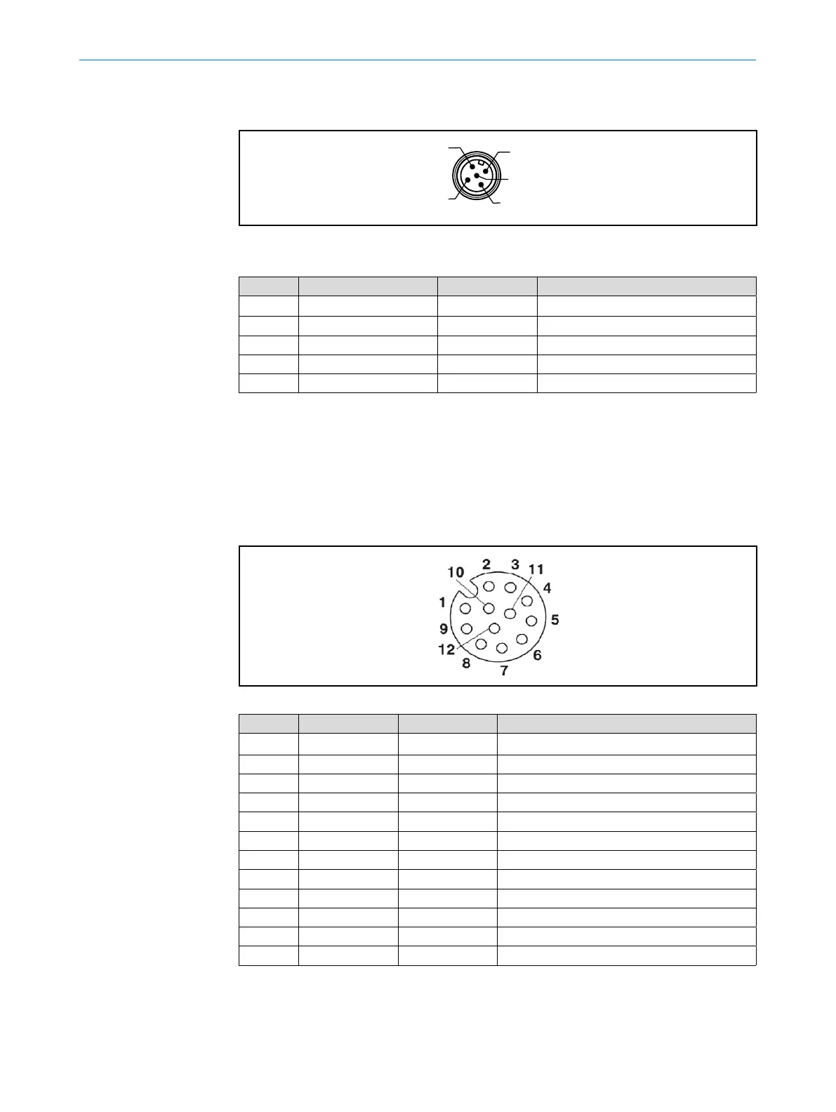
6.2.2 Connection of the digital inputs/outputs
Fig. 18: Pin assignment of the "I/O" connection ( M12×12 socket , A coding).
Pin Wire color Signal Function
1 Brown 24 V EXT Power supply digital outputs 3 to 6
2 Blue GND IN Ground digital inputs 1 + 2
3 White IN1 Digital input 1
4 Green GND ENC Ground encoder inputs
5 Pink IN2 Digital input 2
6 Yellow ENC1 Encoder input 1
7 Black GND EXT Ground digital outputs 3 to 6
8 Gray ENC2 Encoder input 2
9 Red OUT3 Digital output 3
10 Violet OUT4 Digital output 4
11 Gray/pink OUT5 Digital output 5
12 Red/blue OUT6 Digital output 6
Tab. 6: Pin assignment of the "I/O" connection
Pre-assembledconnectioncableswithyingleadsareavailableasaccessories(see
"12.2 Accessories“ on page 77).
Note