OPERATING INSTRUCTIONS | Bulkscan LMS511 8014829/ZNC5/2017-06-06 | SICK
Subject to change without notice
42
ELECTRICAL INSTALLATION
6.3 Wiring the inputs and outputs to the external components
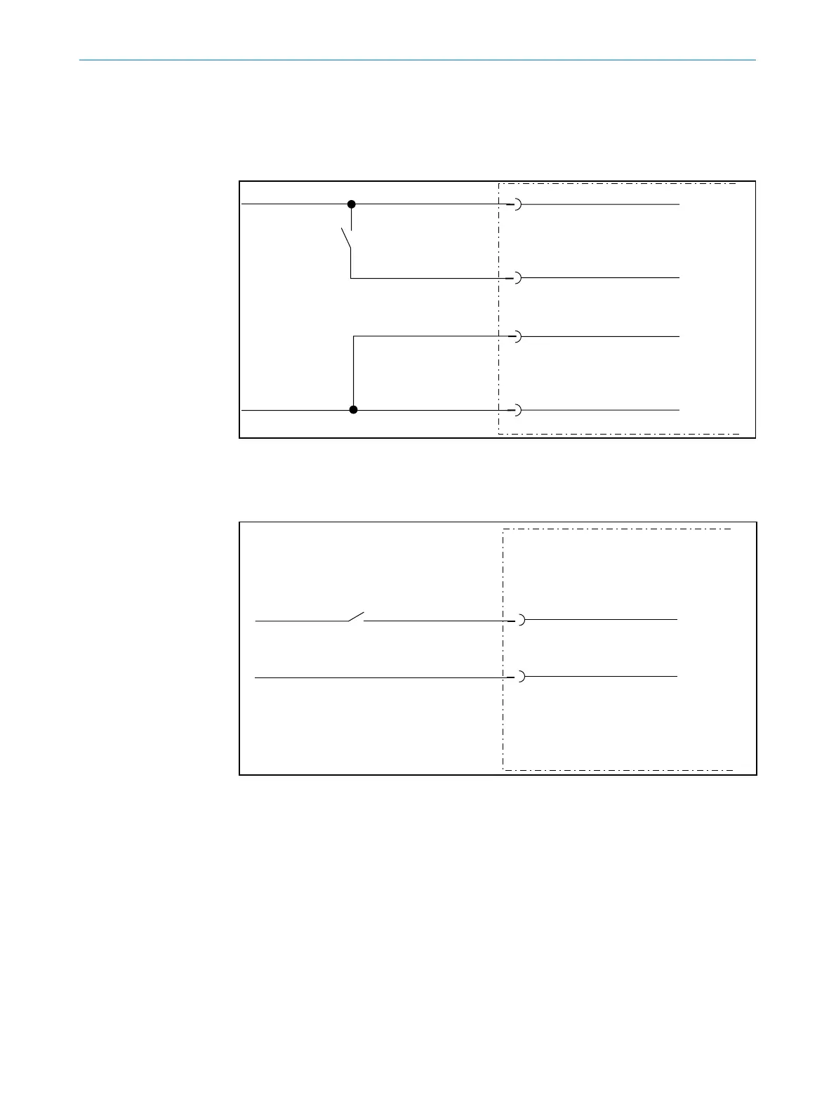
6.3.1 Wiring non-oating digital inputs
External Switch
Bulkscan
24 V
SYS = 19.2 … 28.8 V DC
IN1 or IN2
GND IN
GND SYS
Fig. 22: Wiring non-oating digital inputs
6.3.2 Wiring oating digital inputs
IN1 or IN2
GND IN
External signal source
U
IN
= 11 … 30 V DC
Bulkscan
Fig. 23: Wiring oating digital inputs
The inputs require a switching voltage of at least 11 V. For this reason the supply volt-
age must be at least 11 V.
Note
6.3.3 Wiring encoder inputs
Encoder
Bulkscan
ENC1
ENC2
GND ENC
A (0°)
B (90°)
GND Encoder
V
S
Encoder
Fig. 24: Wiring encoder inputs
The encoder requires its own power supply (V
S
encoder and GND encoder).
6.3.4 Input circuits IN1 and IN2
Fig. 25: Input circuits IN1 and IN2
6.3.5 Connecting the outputs to a PLC
+
24 V EXT
OUT1, OUT2
1
4
3
Bulkscan
SPS
2
_
Fig. 26: Connecting the outputs to a PLC (active LOW)
Note
IN1 or IN2
GND EXT
Bulkscan

 Loading...


