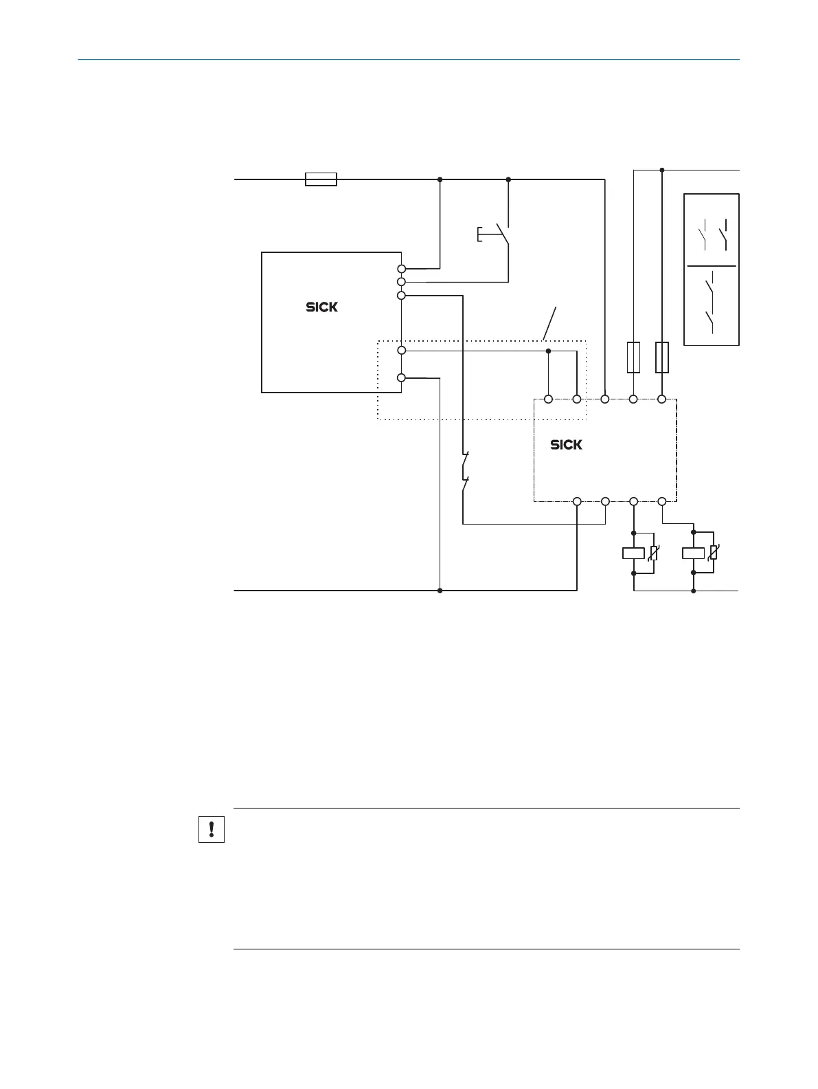
Connection example
T
he following example shows the connection of an FX3-XTIO I/O module to an OSSD1
safety relay. Due to the protected cable laying, SIL3 can be achieved with a single-chan‐
nel output.
32
31I1 I2
24A2 14
23 13
RLY3-OSSD1
FX3-XTIO
A2
Q1
I2
I1
A1
S1
+24 V DC
0 V DC
F0
k2
k1
k2
z
k1 k2
k1
z
x y
x y
F2 F1
K2
K1
2
1
L+
L–
Figure 54: Example for the connection of an FX3-XTIO I/O module to a OSSD1 safety relay
1
Required for SIL3 protected cable laying
2
Output circuits: These contacts must be incorporated into the control such that the
d
angerous state is brought to an end if the output circuit is open. For categories 4 and 3,
they must be incorporated on dual channels (x, y paths). Single-channel incorporation into
the controller (z path) is only possible with a single-channel controller and taking the risk
analysis into account.
5.4.6 Connection of EFI-enabled devices
If the Flexi Soft system contains a FX3-CPU1 main module or higher, the EFI-capable
de
vices and sensors from SICK can be connected to it.
NOTICE
O
vervoltage at the EFI inputs
The device may be damaged if this is not observed.
►
Connect the main module and all EFI-capable devices connected to it with the
same GND connection of the voltage supply.
►
Observe the maximum permissible voltage of ±30V (to terminal A2=GND) at the
EFI inputs.
5 ELE
CTRICAL INSTALLATION
90
O P E R A T I N G I N S T R U C T I O N S | Flexi Soft Modular Safety Controller 8012478/1IG6/2023-02-24 | SICK
Subject to change without notice