3.6.2 Flexi Line
Overview
F
lexi Line allows you to network up to 32 Flexi Soft stations safely. Only main modules
FX3-CPU3 and higher can be used in a Flexi Line system. It is not possible to connect
any of the other main modules (FX3-CPU0, FX3-CPU1, FX3-CPU2).
A single process image is defined for the entire Flexi Line system. Each byte in this
process image is valid either globally, i.e., in the entire system, or locally, i.e., only
for the corresponding station and its neighbor stations. Each Flexi Line station uses
this process image to communicate with its neighbor stations. Thanks to the topology,
addresses are not required in order for communication to take place.
Features
•
S
afe connection of up to 32 Flexi Soft stations via the Flexi Line interface
•
Topology without addresses: If the sequence of the stations changes, simply con‐
firm the new arrangement by performing a teach-in operation.
•
The EFI interface remains available without restrictions:
°
EFI-enabled devices can be connected.
°
A Flexi Link system can be connected.
•
A global process image is defined for all stations.
•
Bytes that are valid globally or locally can be defined in the process image.
•
The process image can contain up to 12 bytes or 96 bits.
•
The maximum cable length between 2 stations is 1,000 meters. The possible total
length of a system with 32 stations is, therefore, 31 kilometers.
System requirements and restrictions
The following minimum system requirements must be met for Flexi Line:
Table 14: System requirements for Flexi Line
System component Version
Hardware FX3-CPU3, every firmware version
Software Flexi Soft Designer version ≥V1.6.0
NOTE
•
Y
ou can even use Flexi Link or EFI communication simultaneously with Flexi Line,
i.e., it is possible to connect either EFI-enabled devices or Flexi Link stations.
•
The process image is transferred from station to station at a fixed update rate.
However, the data is not necessarily processed (logic) at the same time, because
the stations are not synchronized.
•
The update rate of the Flexi Line system is determined by the maximum cable
length between two stations and the size of the process image.
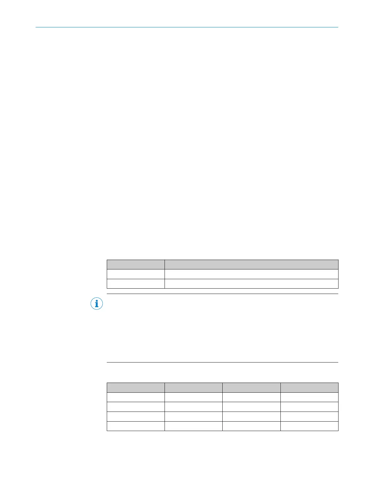
Table 15: Update rate of a Flexi Line system dependent on the maximum cable length and the
si
ze of the process image
Max. cable length 32 bits 64 bits 96 bits
125 m 2 ms 2 ms 4 ms
250 m 2 ms 4 ms 8 ms
500 m 4 ms 8 ms 12 ms
1,000 m 8 ms 12 ms 20 ms
3 PRODUCT DESCRIPTION
46
O P E R A T I N G I N S T R U C T I O N S | Flexi Soft Modular Safety Controller 8012478/1IG6/2023-02-24 | SICK
Subject to change without notice