Figure 23: Internal structure of the UE410-2RO
UE410-4RO
T
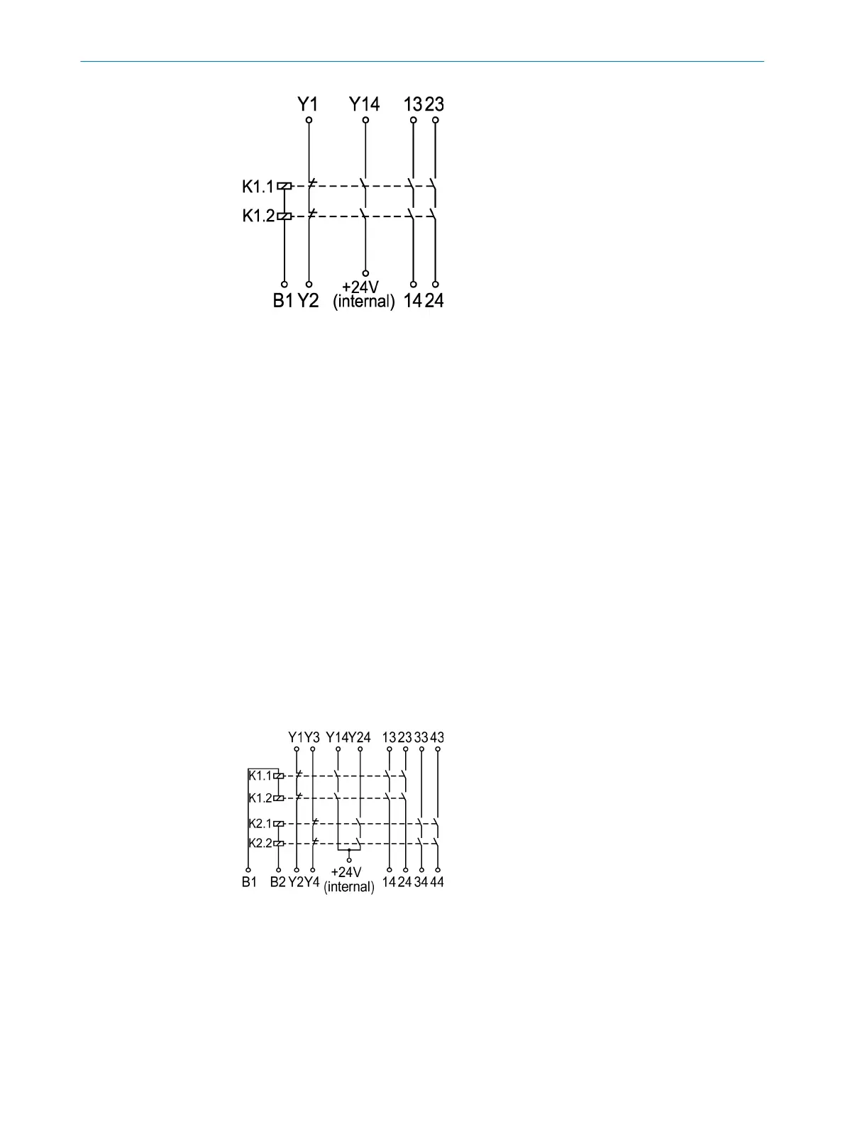
he UE410-4RO relay module has two control inputs (B1, B2). These each control two
internal relays. Two independent, redundant cut-off paths are therefore available.
Control input (B1) actuates two internal relays and provides a redundant cut-off path
consisting of:
•
Two safe enabling current paths (13/14, 23/24), dual-channel and volt-free
•
One signaling current path (Y14), dual-channel and connected internally to 24 V
DC
•
One feedback circuit external device monitoring (Y1/Y2), dual-channel and volt-
free
Control input (B2) actuates two internal relays and provides a redundant cut-off path
consisting of:
•
Two safe enabling current paths (33/34, 43/44), dual-channel and volt-free
•
One signaling current path (Y24), dual-channel and connected internally to 24 V
DC
•
One feedback circuit external device monitoring (Y3/Y4), dual-channel and volt-
free
This means that the UE410-4RO relay module has twice the number of functions as the
UE410-2RO.
Figure 24: Internal structure of the UE410-4RO
3.5 Interfaces
3.5.1 RS-232
Each main module has an RS-232 interface with the following functions:
3 PRODUCT DESCRIPTION
42
O P E R A T I N G I N S T R U C T I O N S | Flexi Soft Modular Safety Controller 8012478/1IG6/2023-02-24 | SICK
Subject to change without notice