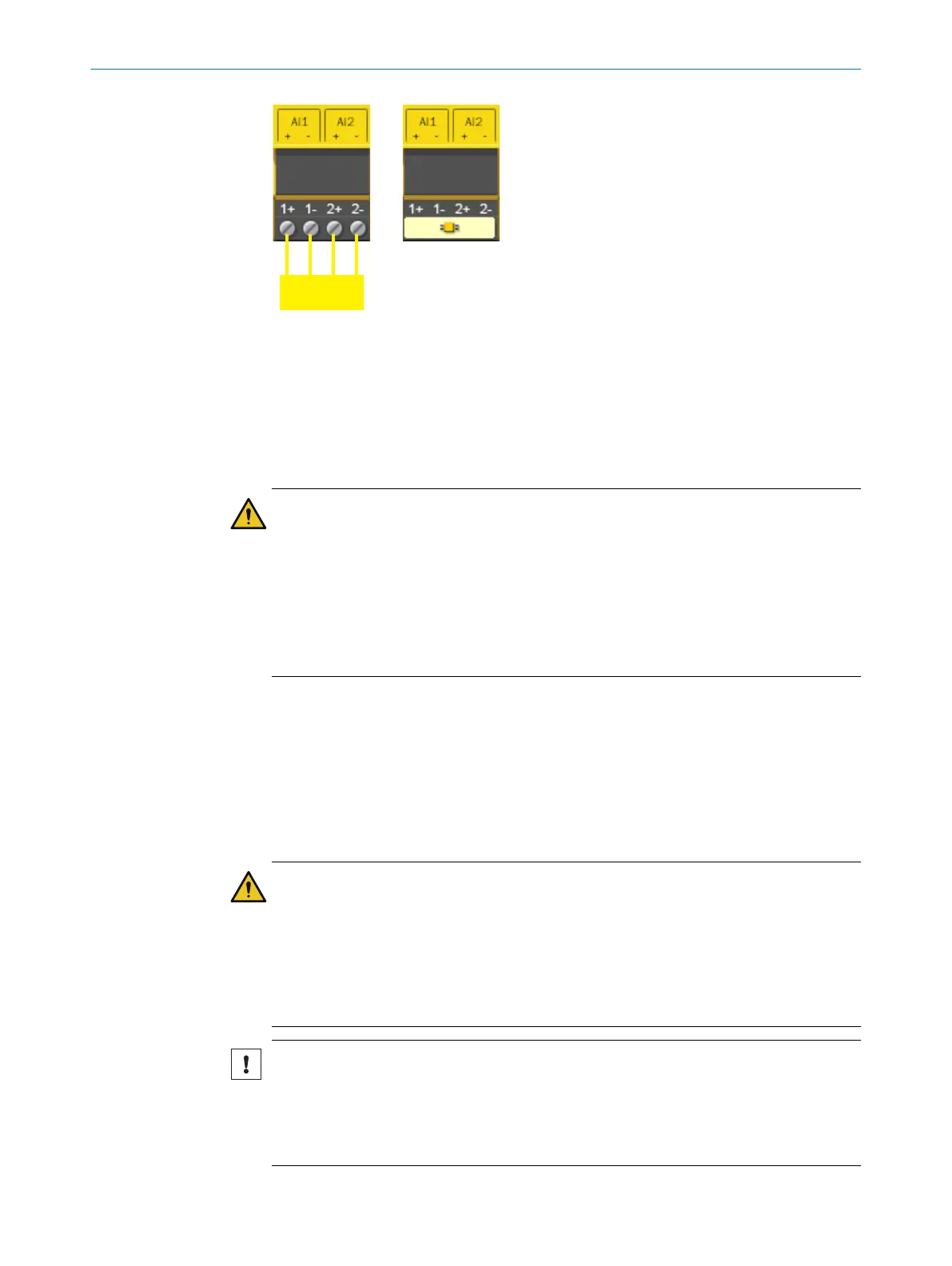
Figure 58: Connection of a safe dual-channel analog signal transmitter
Left: Connection example
Ri
ght: As illustrated in Flexi Soft Designer
Connecting the sensors to a second control
T
he FX3-ANA0 inputs are configured in such a way that a second control (connected in
series) can use the measured values of the sensors as well.
WARNING
Inf
luence of the signals of the FX3-ANA0due to the memorized fault current of a
second control
The dangerous state may not be stopped or not be stopped in a timely manner in the
event of non-compliance.
The target safety-related level may not be achieved in the event of non-compliance.
►
Carry out the corresponding safety assessment and validation, taking into account
this possible source of error.
5.4.10 Connecting Flexi-Link system
Overview
There are two ways to connect a Flexi Link system:
•
Connection via EFI1 (26 bits)
•
Connection via EFI1+2 (52 bits)
Important information
WARNING
L
imited safety due to buffering elements
The target safety-related level may not be achieved in the event of non-compliance.
►
In a Flexi Link system, do not use buffering elements such as CAN bridges, CAN
repeaters or CAN-capable optical photoelectric sensors.
►
Do not use any other components except for Flexi Link stations in a Flexi Link
system.
NOTICE
O
vervoltage at the EFI inputs
The device may be damaged if this is not observed.
►
Observe the maximum permissible voltage at the EFI inputs of ±30V (to terminal
A2=GND).
5 ELECTRICAL INSTALLATION
98
O P E R A T I N G I N S T R U C T I O N S | Flexi Soft Modular Safety Controller 8012478/1IG6/2023-02-24 | SICK
Subject to change without notice