NOTE
W
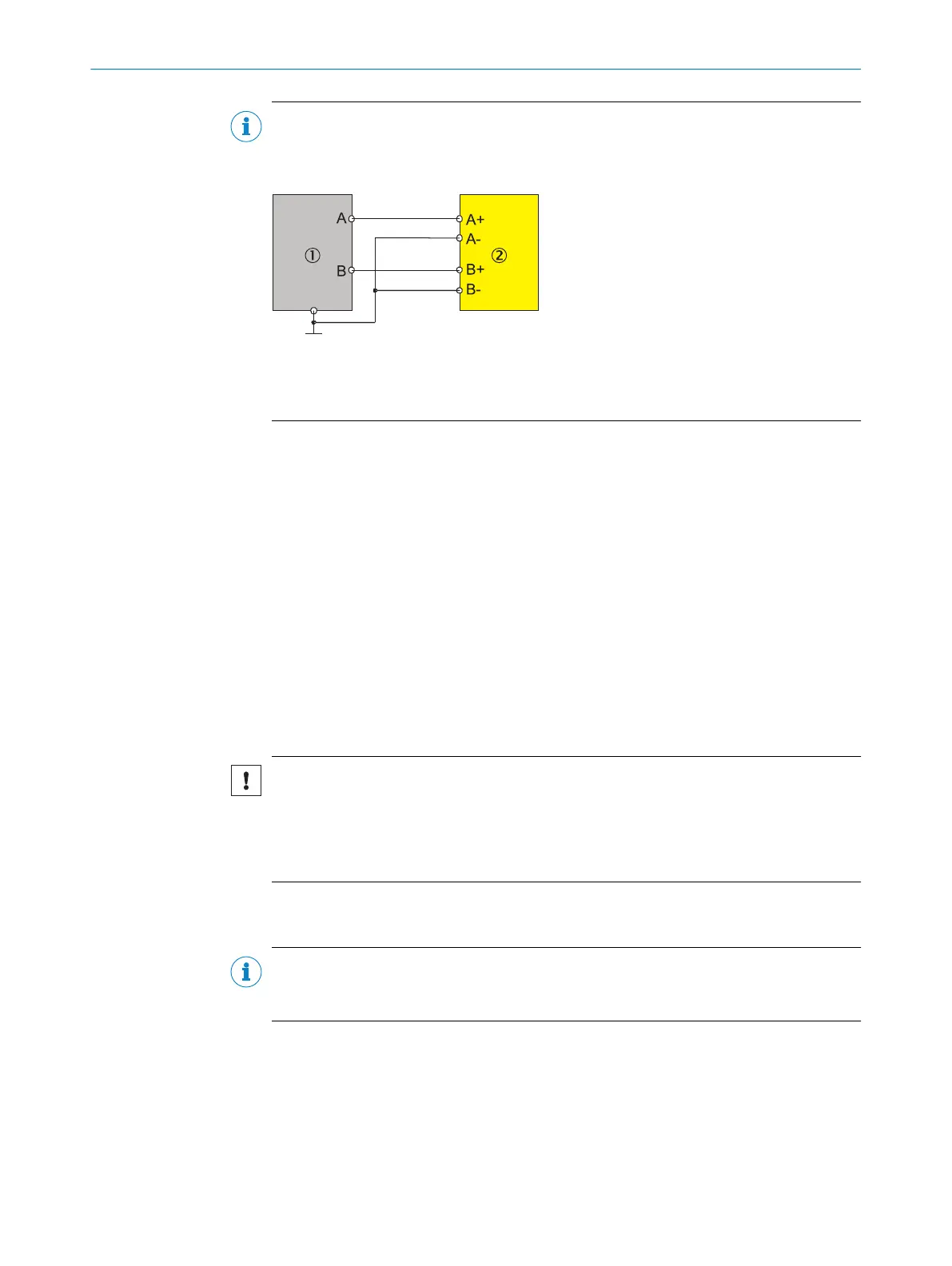
here encoders with two outputs are concerned, inputs A– and B– on the FX3-MOCx
must not remain open; they must be connected to 0V. In this case, the connection
must be as close as possible to the 0V encoder connection.
Figure 55: Connection of A/B incremental encoders with two outputs
1
A/B incremental encoder with two outputs
2
FX3-MOCx
24V are available at the encoder connection of the FX3-MOC0 module for the encoder
v
oltage supply. A selectable supply voltage is available at the encoder/motor feed‐
back connection boxes. Details:
•
see "Encoder/motor feedback connection units", page 61
•
see "Motion Control MOC0", page 154 (technical data)
•
see "Motion Control MOC1", page 159 (technical data)
•
see "EBX1, EBX3 and EBX4 encoder/motor feedback connection units", page 165
(technical data)
5.4.9 Connecting analog sensors
Two analog sensors can be connected to the FX3-ANA0 analog input module in order
to measure a joint process variable. The analog input module has two analog inputs,
which are continually compared with one another.
Only sensors with a standardized current interface in accordance with EN61131-2
5.3.1 and with a signal strength of4 to 20mA can be connected and evaluated.
NOTICE
Ex
ceeding the limit values at the inputs
The device may be damaged if this is not observed.
►
Observe the limit values for the inputs (30V DC/30mA).
►
Only use suitable sensors.
The AI1 sensor input consists of pins 1+ and 1–. The AI2 sensor input consists of pins
2+ and 2–.
NOTE
T
he FX3-ANA0 can detect a sensor connection with reverse polarity (I1+ switched with
I1– or I2+ switched with I2–) as an error.
If only one individual sensor is used for a process variable, this sensor must be con‐
nec
ted in series to both inputs; see figure 57.
Sensor connection cables
The FX3-ANA0 analog input module has no shielding connections. If shielding is
required for connecting the sensors – for reasons of electromagnetic compatibility,
for example – the shield must be connected using a ground terminal that is positioned
in the control cabinet close to the Flexi Soft main module.
5 ELE
CTRICAL INSTALLATION
96
O P E R A T I N G I N S T R U C T I O N S | Flexi Soft Modular Safety Controller 8012478/1IG6/2023-02-24 | SICK
Subject to change without notice