NOTE
C
onnected sensors are not supplied by the FX3-ANA0. They require an external power
supply unit.
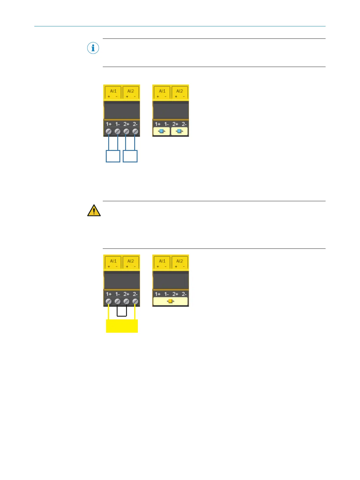
Connection examples
Figure 56: Connection of non-safe single-channel analog signal transmitters
Left: Connection example
Ri
ght: As illustrated in Flexi Soft Designer
WARNING
Ine
ffectiveness of the protective device due to improper connection
The target safety-related level may not be achieved in the event of non-compliance.
►
When using a safe single-channel analog signal transmitter, install a bridge
between the connections AI1– and AI2+, see figure 57.
Figure 57: Connection of a safe single-channel analog signal transmitter
Left: Connection example
Ri
ght: As illustrated in Flexi Soft Designer
ELECTRICAL INSTALLATION 5
8012478/1IG6/2023-02-24 | SICK O P E R A T I N G I N S T R U C T I O N S | Flexi Soft Modular Safety Controller
97
Subject to change without notice