Product description
FLOWSIC200 · Operating Instructions · 8013271/1CJ9/V2-0/2022-01 · © SICK Engineering GmbH 25
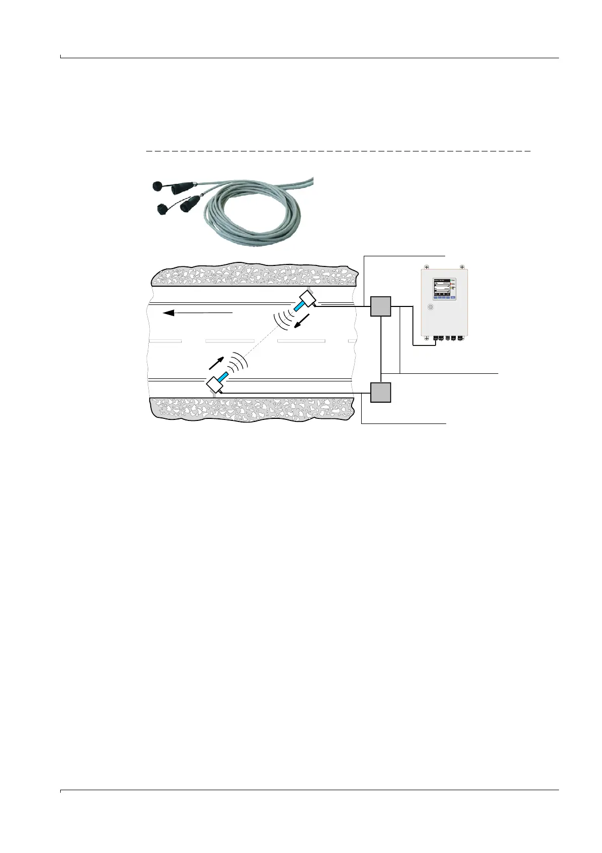
2.2.4 Connection cable
The sender/receiver units are connected to the junction boxes using cables included in the
scope of delivery. The junction boxes must be connected to the MCU control unit using
cables provided by the customer (information on cable types and wiring
p. 43, §3.3.2).
Fig. 10 Connection cable
On-site cables, (e.g. type
Li2YCY(TP) 2x2x0.5 mm²)
Connection cable halogen-free (9-core)
3 x 2 x 0.25 + 3 x 1.0 mm², length 2 m or 25 m (SICK
scope of delivery)
Connection cable SICK
Connection cable SICK
Flow direction