Assembly and installation
FLOWSIC200 · Operating Instructions · 8013271/1CJ9/V2-0/2022-01 · © SICK Engineering GmbH 41
3.2.6 Installing the MCU control unit
The control unit must be mounted on a vertical, level base at an easily accessible, well
protected location as shown in Fig.25.
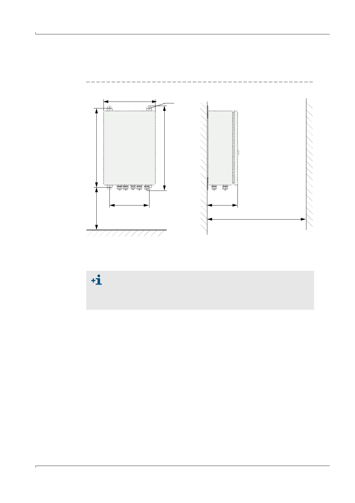
Fig. 25 MCU installation dimensions in wall housing
The respectively suitable mounting kits can be used for fastening (
p. 26, §2.2.5;
installation
p. 34, Fig. 14).
210
> 350
120
> 250
340
320
M8
Clearance for cables
160
Clearance for door swing area,
minimum sideways distance to passing
vehicles when fitted on the tunnel wall
When using suitable cables (
p. 55, §4) , the control unit can be positioned
up to 1000 m away from the sender/receiver units (use bus wiring
according to p. 48, Fig. 29; length is overall length of all cables used).
We recommend installing the MCU in a control room or similar for trouble-
free communication with the FLOWSIC200.