86 FLOWSIC200 · Operating Instructions · 8013271/1CJ9/V 2-0/2022-01 · © SICK Engineering GmbH
Commissioning and parameterization
4.3.1.2
Digital outputs
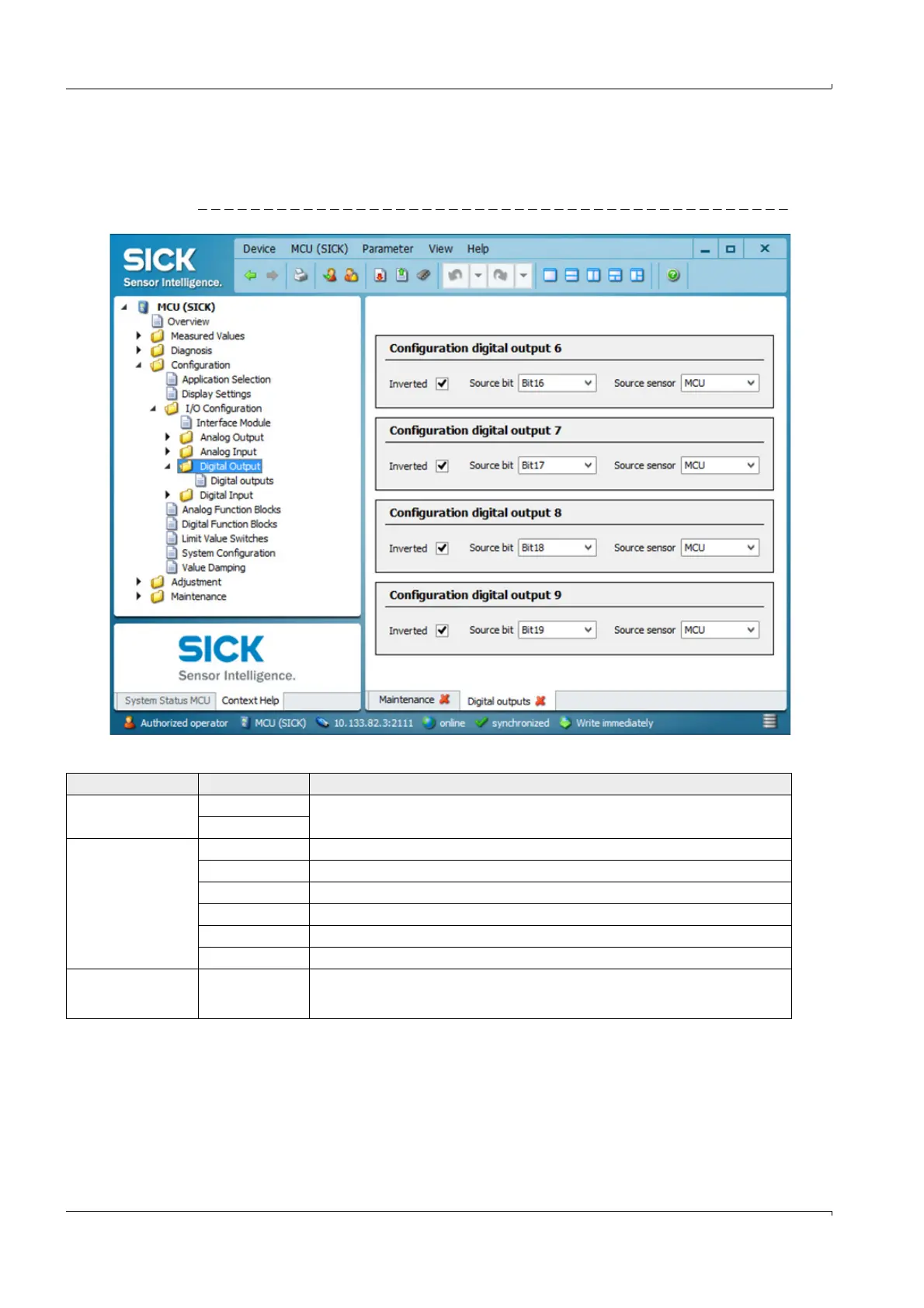
Select the ”Configuration / I/O Configuration / Digital Output / Digital outputs” directory for
entering parameters.
Fig. 77 ”Configuration / I/O Configuration / Digital Output / Digital outputs” directory
Field Parameter Remark
Inverted Inactive Define the switching direction
Active
Source bit Bit 0 Malfunction
Bit 1 Maintenance
Bit 2 Maintenance request
Bit 3 Function check
Bit 7 Operation ( no malfunction)
Bit 16 to 31 Aim bit of the limit value switch (
p. 88, Fig. 79)
Source sensor Selection of the component:
- Sensor 1 to 8 when the device status is to be output
- MCU when limit values are to be signaled