Commissioning and parameterization
FLOWSIC200 · Operating Instructions · 8013271/1CJ9/V2-0/2022-01 · © SICK Engineering GmbH 87
Verifying settings
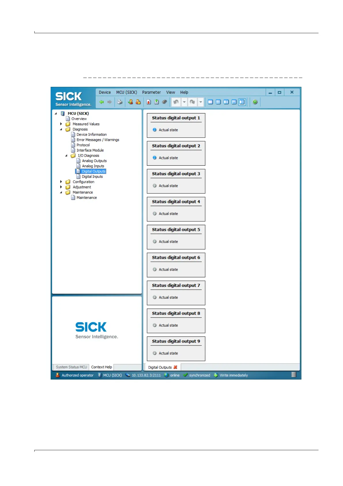
The current status of each relay is shown in the “Diagnosis / I/O Diagnosis / Digital
Outputs” directory.
Fig. 78 “Diagnosis / I/O Diagnosis / Digital Outputs” directory
To check whether relays switch as intended, measured values which exceed the
parameterized limits must be created.
In addition, a continuity tester can be connected to the respective relay output for an
external check.