Assembly and installation
FLOWSIC200 · Operating Instructions · 8013271/1CJ9/V2-0/2022-01 · © SICK Engineering GmbH 45
3.3.2.2
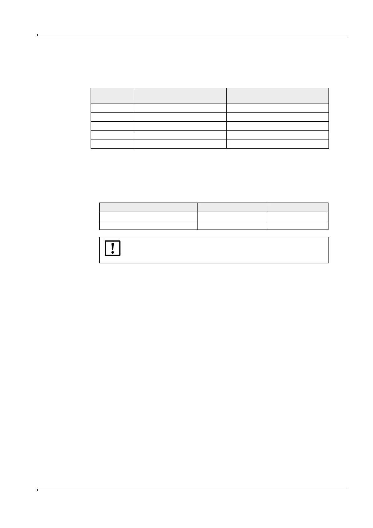
Cable lengths
When connecting bus versions with several sensors (
p. 15, Fig. 3), the maximum cable
length is reduced as follows depending on the number of measuring points connected:
Proceed as follows when longer cable lengths are used to connect several sensors:
1 Use larger diameter e.g. cable type with 3 or 4 pairs of wires and 2 pairs of wires for
power supply
To ensure the power supply for long cable lengths, the following key data for the
FLOWSIC200 must be observed when selecting the wire diameter:
2 Use an MCU with more powerful power supply unit
Both solutions are available from the manufacturer on request.
3.3.3 Connecting sender/receiver units and junction boxes
These components are to be interconnected as shown in p. 48, Fig. 29:
– Between the sender/receiver unit and the junction box using the cables with connector
included in the scope of delivery,
– Between junction boxes and MCU with cable provided by customer.
Number of
measuring points
Cable type 2 x 2 x 0.5 mm
2
(e. g. UNITRONIC Li2YCYv(TP))
Cable type 3 x 2 x 0.25 + 3 x 1.0 mm
2
(e.g. UNITRONIC FD P BUS Combi)
1 1000 m 1000 m
2 500 m 1000 m
3 330 m 660 m
4 250 m 500 m
5 200 m 400 m
Sender/receiver unit supply Type 200M Type 200H, 200HM
Current consumption per FLSE200 35.5 mA 38 mA
Required voltage to the FLSE200 18 - 24 VDC 18 - 24 VDC
NOTICE:
The maximum cable length is 1000 m even when using larger wire
diameters.