Assembly and installation
FLOWSIC200 · Operating Instructions · 8013271/1CJ9/V2-0/2022-01 · © SICK Engineering GmbH 35
3.2.2 Setting the bus systems
3.2.2.1 Check the termination
The connection between the sender/receiver units and the MCU must be terminated at
both ends with resistors. These are already present on the boards (jumpers).
To check/change the termination, open the MCU and sender/receiver units, position the
jumpers on the respective pins depending on the MCU layout, and then close the device
components again.
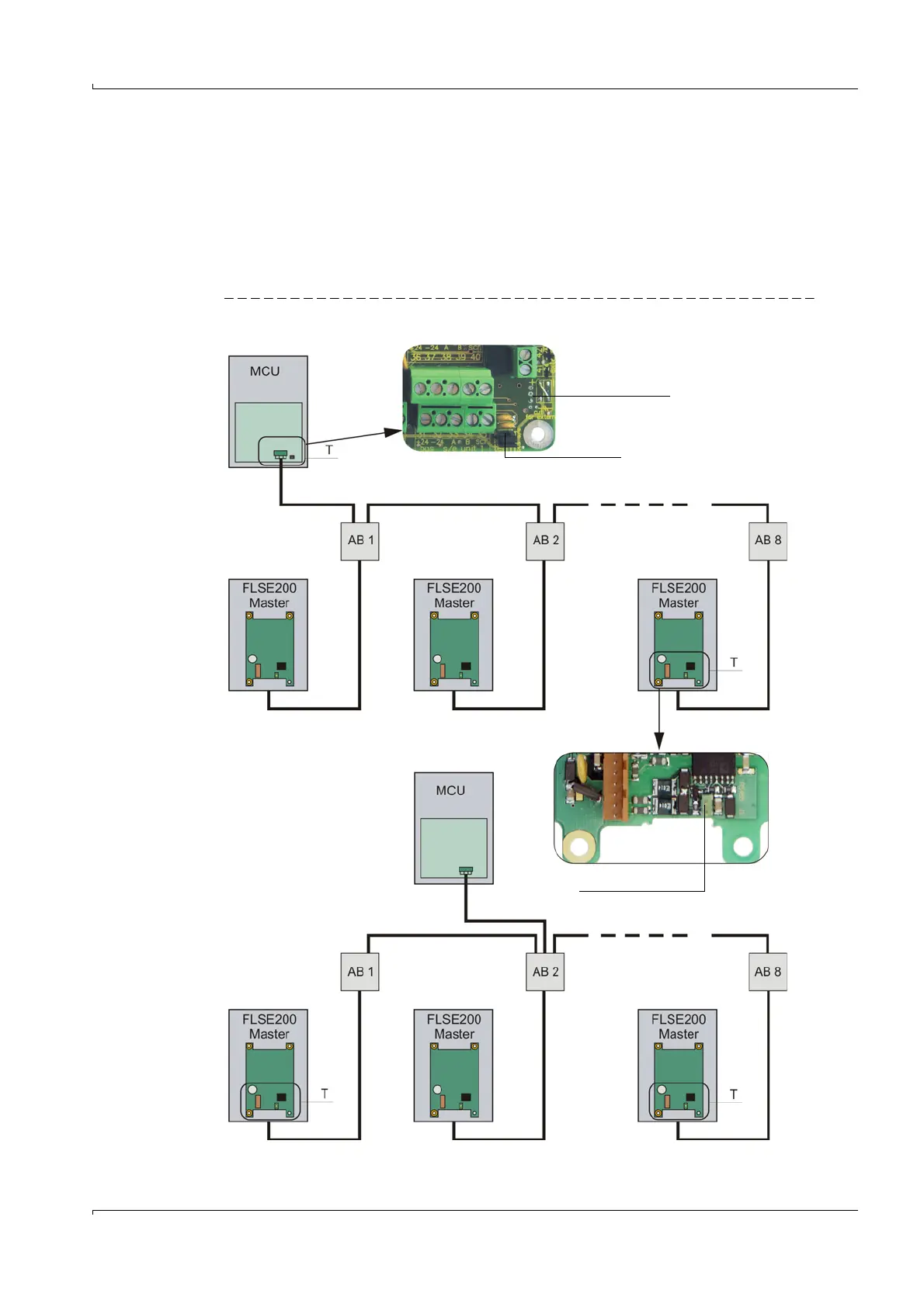
Fig. 15 Termination
MCU at bus start
Processor board
Jumper
MCU in bus middle
Slot for jumper
AB x = junction box option
T = termination