Commissioning and parameterization
FLOWSIC200 · Operating Instructions · 8013271/1CJ9/V2-0/2022-01 · © SICK Engineering GmbH 75
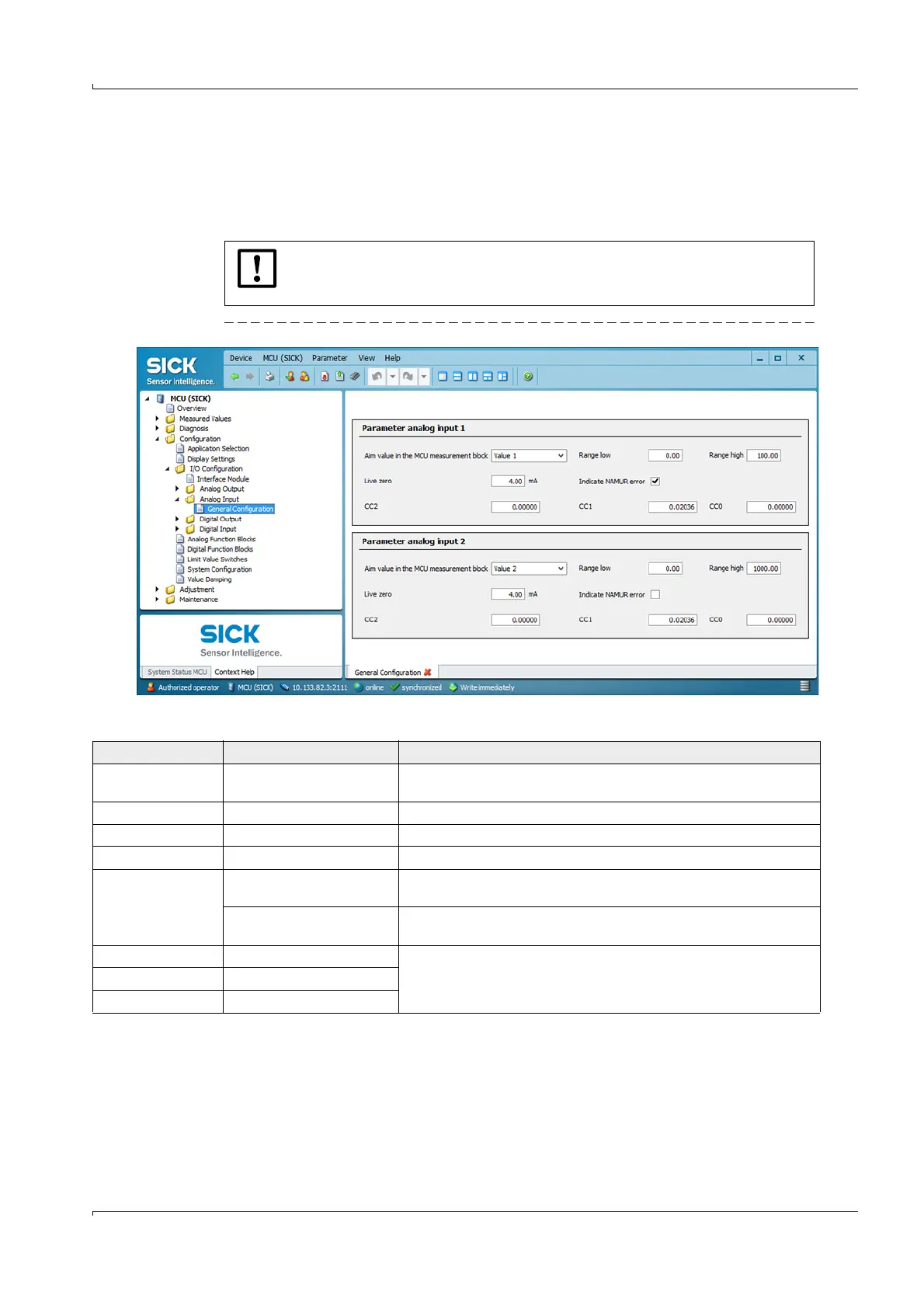
4.2.7 Configuring the analog inputs
In directory “Configuration / I/O Configuration / Analog Input / General Configuration”, the
standard analog inputs can be assigned to any measured values to be standardized in the
“Parameter analog input 1” and ”Parameter analog input 2” groups, and the respective
measuring range can be defined.
Fig. 62 Directory “Configuration / I/O Configuration / Analog Output / Analog Input“(example)
NOTICE:
Correction factors CC2, CC1 and CC0 are preset at the factory and may only be
changed by SICK Service.
Field Parameter
Remark
Aim value in the MCU
measurement block
Measured value 1 to 8 Variable to be assigned to the selected analog input
Range low Lower measuring range limit Physical value at live zero
Range high Upper measuring range limit Physical value at maximum current
Live zero Zero point value > 0 mA) Specification of the mA value for measurement range start
Indicate NAMUR error Inactive No error is reported for underflow or overflow of the set current range
(LZ to 20 mA).
Active An error is reported for underflow or overflow of the set current range
(LZ to 20 mA).
CC2 Square correction factor Correction factors for calibrating the input size (factory preset)
Modification only by SICK Service!
CC1 Linear correction factor
CC0 Absolute correction factor