76 FLOWSIC200 · Operating Instructions · 8013271/1CJ9/V 2-0/2022-01 · © SICK Engineering GmbH
Commissioning and parameterization
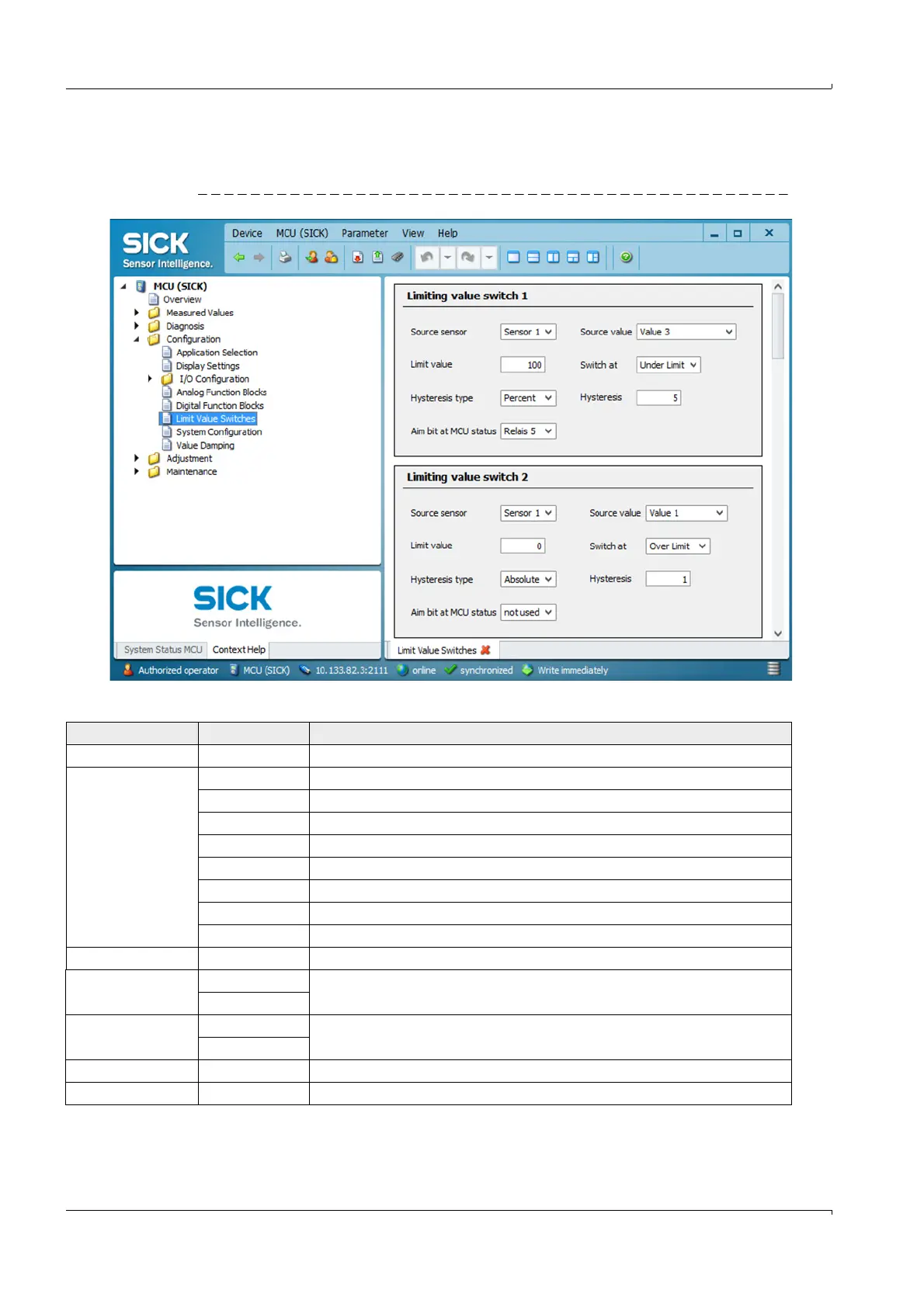
4.2.8 Configuring the limit value relay
Select directory “Configuration / Limit Value Switches” for configuring.
Fig. 63 ”Configuration / Limit Value Switches” directory
* Not relevant for FLOWSIC200
Field Parameter Remark
Source sensor Sensor 1 to 8 Sensor for which a limit value is to be assigned to the output signal.
Source Value Measured value 1 Volume flow in operating conditions*
Measured value 2 Flow velocity
Measured value 3 Sound velocity
Measured value 4 Acoustic temperature
Measured value 5 Temperature A*
Measured value 6 Temperature B*
Measured value 7 Signal to noise ratio A
Measured value 8 Signal to noise ratio B
Limit value Value The limit value relay switches when the entered value is overflown or underflown.
Switch at Over Limit Define the switching direction
Underflow
Hysteresis
type
Percent Assignment of the value entered in the “Hysteresis type” field as relative or absolute
value of defined limit value
Absolute
Hysteresis Value Define a tolerance for resetting the limit value relay
Aim bit at MCU status Relay 5 Aim bit at MCU status = special memory in the MCU for monitoring limit values