Assembly and installation
FLOWSIC200 · Operating Instructions · 8013271/1CJ9/V2-0/2022-01 · © SICK Engineering GmbH 37
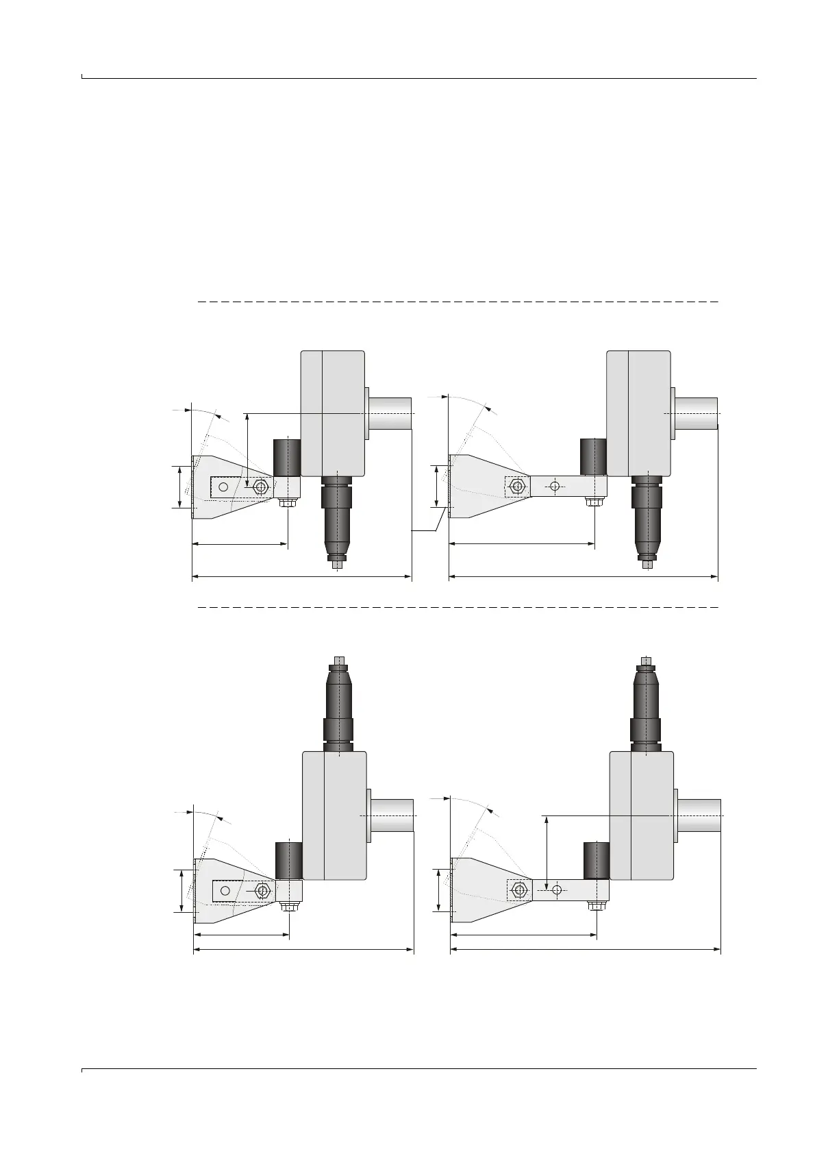
3.2.3 Fitting the sender/receiver units
Attach the sender/receiver units to the fitted brackets. Arrange with the connection line
downwards (
Fig. 17 and
p. 38, Fig. 19, as well as
p. 39, Fig. 21) should be preferred.
For precise alignment to each other according to
p. 39, §3.2.4, the sender/receiver units
can be rotated vertically and tilted horizontally over a wide range. This allows easy
adaptation to local conditions such as the slope of the tunnel wall, road inclination, curves.
The two mounting holes in the part of the bracket that is directly connected to the sender/
receiver unit serve to increase or extend the swivel range in the horizontal direction.
FLSE200-M sender/receiver unit
Fig. 17 Positioning with connection line from below
Fig. 18 Positioning with connection line from above
Reduced swivel range Extended swivel range
90
210
125
245
40
40
70
3
0
°
2
0
°
M 8
Reduced swivel range Extended swivel range
90
210
125
245
40
40
70
3
0
°
2
0
°