Commissioning and parameterization
FLOWSIC200 · Operating Instructions · 8013271/1CJ9/V2-0/2022-01 · © SICK Engineering GmbH 89
4.3.2 Configuring optional Interface modules
4.3.2.1 General information
The following steps are necessary to select and set the optionally available Interface
modules Profibus DP, Ethernet, Ethernet 3-fold, Modbus RS485 and Modbus TCP:
Select device file “MCU”, set the measuring system to “Maintenance” mode and enter
the Level 1 password (
p. 64, §4.1.4).
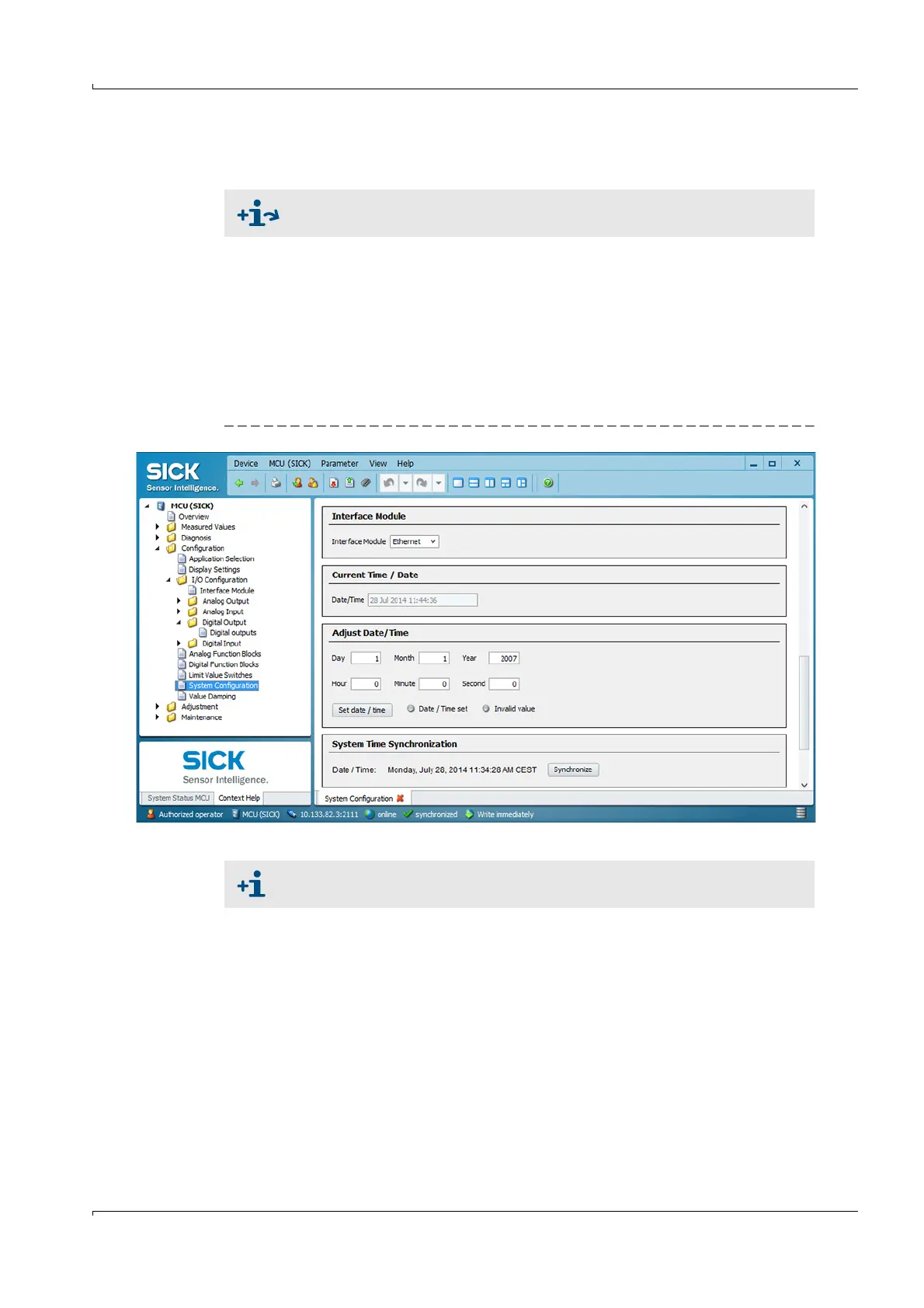
Switch to the “Configuration / System Configuration” directory.
The field “Interface Module” shows the installed Interface module.
Configure the interface module according to requirements.
Set the measuring system back to the operating state.
Fig. 80 Directory “Configuration / System Configuration”
For detailed information on the individual modules see “Interface
documentation FLOWSIC200“.
GSD file and measured value assignment are available for the Profibus DP
module on request.