32 FLOWSIC200 · Operating Instructions · 8013271/1CJ9/V 2-0/2022-01 · © SICK Engineering GmbH
Assembly and installation
3.1
Project planning
3.1.1 Planning steps
Plan the following before starting assembly and installation work:
Determine measuring location(s).
Select system components according to
p. 18, §2.2 meeting the conditions of use and
customer requirements.
Define installation locations for sender/receiver units, MCU and junction boxes.
Plan power supply.
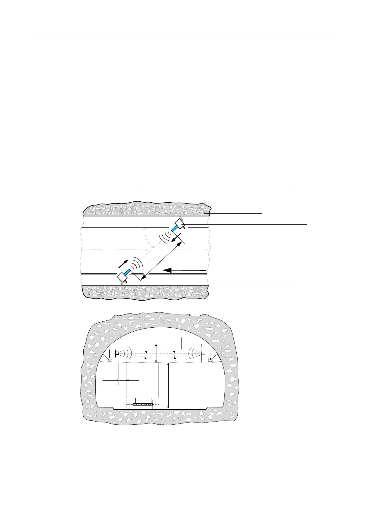
3.1.2 Requirements for the installation location for the sender/receiver units
The master and slave sender/receiver units must be installed on opposite tunnel walls at a
sufficient height above the road surface, offset to the side (
Fig. 12). The angle between
the measuring axis and tunnel axis should not be significantly greater than 60° (minimum
value 45°).
Fig. 12 Installation location for sender/receiver units
45 ... 60°
M
e
a
s
u
r
i
n
g
d
i
s
t
a
n
c
e
Max. permissible
vehicle height
Max. 5 °
> 0.5 m
> 2 m
Clearance
Tunnel wall
Sender/receiver unit, Master
Sender/receiver unit, Slave
Flow direction