Assembly and installation
FLOWSIC200 · Operating Instructions · 8013271/1CJ9/V2-0/2022-01 · © SICK Engineering GmbH 33
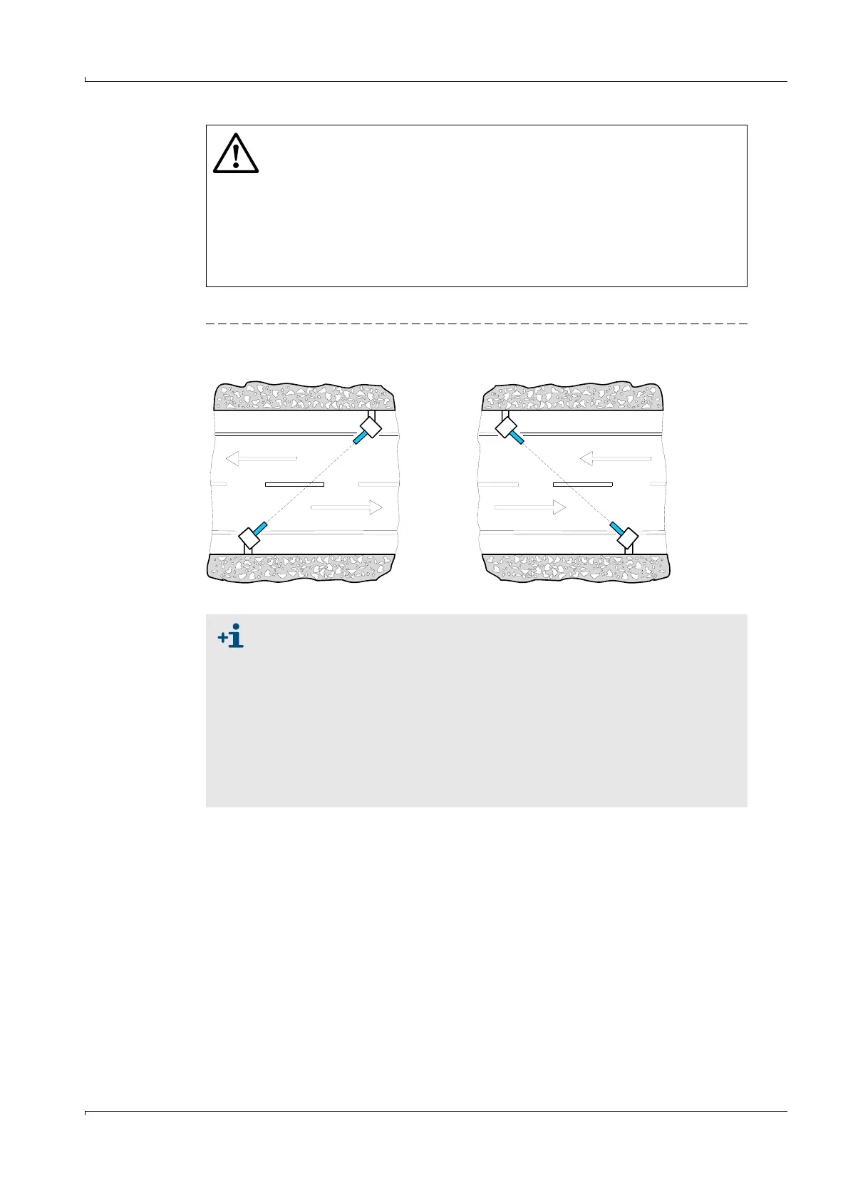
Fig. 13 Arrangement of sender/receiver units
WARNING:
The measuring distance between the opposite sender/receiver units must
be free of fixtures or similar to ensure unobstructed sound propagation
(observe clearance as specified in
p. 32, Fig. 12).
The minimum distance to passing vehicles must be maintained (
p. 32, Fig.
12).
Arrange the sender/receiver units so that as little splash water and dirt as
possible can hit the transducers, i.e. with the direction of travel of the
vehicles (
Fig. 13).
Correct Incorrect
Traffic
Traffic Traffic
Traffic
If, due to structural conditions, the measurement axis has to be set so low
that the maximum permissible vehicle height reaches into the necessary
clearance, the measurement can be interrupted in the event of traffic
congestion.
If the required distance between the measurement axis and tunnel ceiling
cannot be maintained, especially in the case of rectangular tunnel cross-
sections, sound reflections can occur on the tunnel ceiling with resulting
measurement disturbances.
This can be remedied by slightly tilting the measuring axis of both sender/
receiver units downward by max. 5° (
p. 32, Fig. 12) or by installing sound-
absorbing materials on the tunnel ceiling.