34 FLOWSIC200 · Operating Instructions · 8013271/1CJ9/V 2-0/2022-01 · © SICK Engineering GmbH
Assembly and installation
3.2
Assembly
All of the installation work has to be carried out by the customer. This includes:
Fitting the brackets for the sender/receiver units.
Configuring the bus systems (when used).
Fitting the sender/receiver units, junction boxes and MCU.
3.2.1 Fitting the brackets for the sender/receiver units
The brackets are fastened to the tunnel wall/ceiling with the respective required mounting
kit (selection according to Section
p. 26, §2.2.5). The following steps are then necessary:
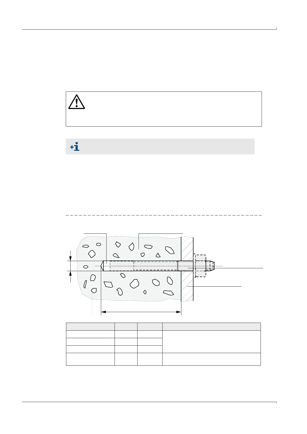
Drill 2 holes 40 mm apart (drill hole dimensions
Fig. 14).
Insert anchor bolts (mounting kits 2D4/2D8/4D8-1.4571/PA, 2M8-1.4571) or anchor
bolts (mounting kit 2M8/4M8-1.4529).
Fasten the brackets with the hexagon head screws or nuts.
Fig. 14 Drill hole dimensions
WARNING:
Observe the relevant safety regulations as well as the safety notices in
Section 1 during all assembly work!
If possible, only carry out assembly work when the tunnel is closed!
Take suitable protective measures against possible hazards!
All dimensions in mm.
T
D
Drill hole Tunnel wall / ceiling
Anchor bolts
with lock nut
Bracket
Mounting kit Dia. Depth Remark
2D4-1.4571/PA 6 40 The dowel should be flush with the tunnel wall/
ceiling
2D8/4D8-1.4571/PA 10 70
2M8-1.4571 12 60
2M8/4M8-1.4529 8 65 The anchor bolt must not protrude more than
12 mm from the tunnel wall/ceiling