Assembly and installation
FLOWSIC200 · Operating Instructions · 8013271/1CJ9/V2-0/2022-01 · © SICK Engineering GmbH 39
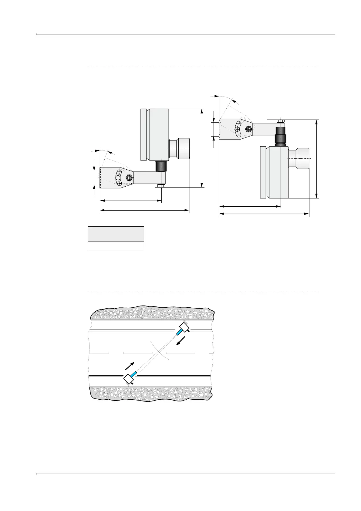
FLSE200-H / FLSE200-HM sender/receiver unit
Fig. 21 Installing the FLSE200-H / FLSE200-HM sender/receiver unit
3.2.4 Aligning the sender/receiver units
After installation, the sender/receiver units must be aligned so that the respective
transmission directions match (
Fig. 22 and
p. 40, Fig. 23).
Fig. 22 Permissible swivel range in flow direction
180
a
40
(228)
2
0
°
180
a
40
(228)
3
0
°
Standing positioning Hanging positioning
FLSE200-H
FLSE200-HM
a =263