Product description
FLOWSIC200 · Operating Instructions · 8013271/1CJ9/V2-0/2022-01 · © SICK Engineering GmbH 27
2.3
Computations
2.3.1 Flow velocity calibration
When the measured velocity does not agree with the mean value of the flow velocity in the
entire tunnel cross-section, the FLOWSIC200 can be calibrated by a network measurement
with a comparison measuring system. Regression coefficients Cv2, Cv1 and Cv0 are
determined from the measured values of the two measuring systems, which are entered
into the FLOWSIC200 during parameterization (
p. 92, §4.3.3). The device then calculates
the calibrated flow velocity v from measured value x of the FLOWSIC200 according to the
following formula:
v = Cv2 · x² + Cv1 · x + Cv0
If no calibration is required, Cv2, Cv0 = 0, Cv1 = 1 (default factory setting). The value x then
corresponds to the representative velocity.
2.3.2 Temperature calibration
The calibration of the temperature measurement with the FLOWSIC200 can be done by a
comparison measurement with a separate temperature sensor (e.g. Pt100), but is
generally not necessary, since the active measuring distance can be determined extremely
accurately (± 1 cm) (see formula 2.6,
p. 16, §2.1.3 ).
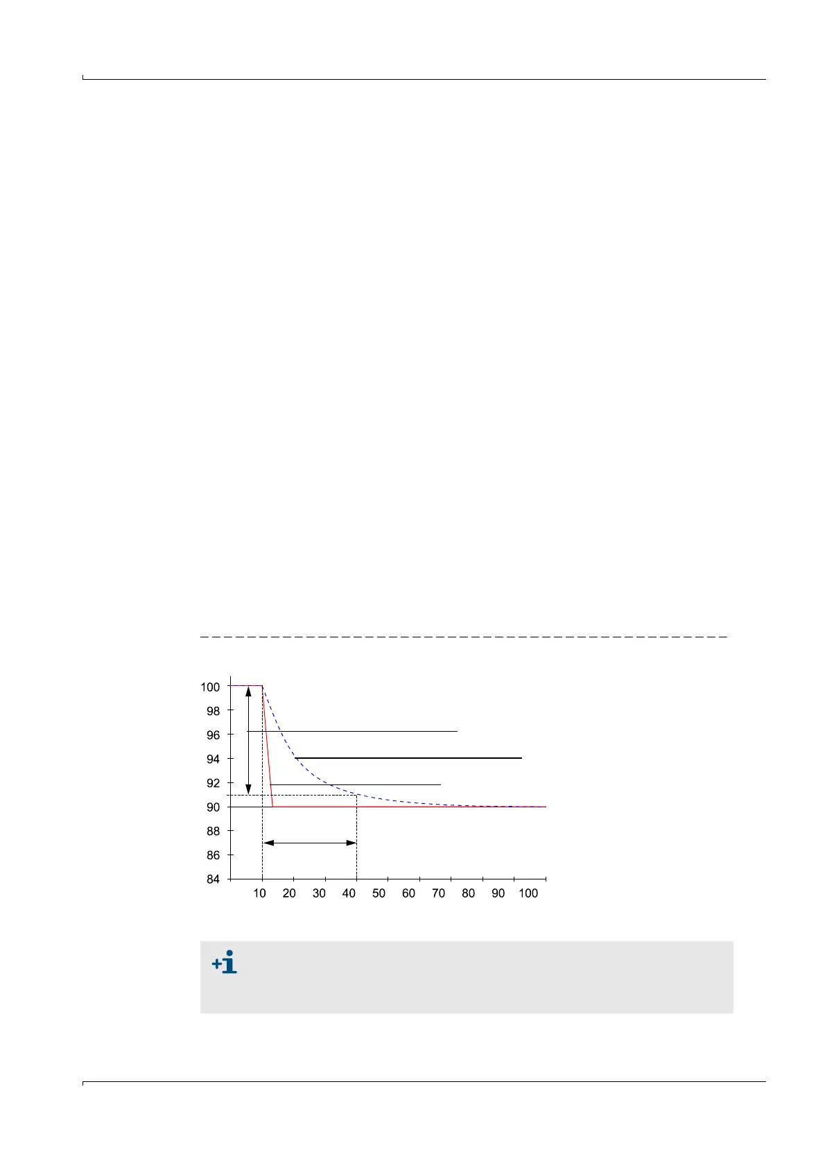
2.3.3 Response time
The response time is the time taken by the measuring device to reach 90% of the end value
after a sudden change in the measured value (
Fig. 11).
The response time can be set to any value in the range 1...300 (typical: 60 ... 90 s). Setting
a higher response time provides better attenuation of transient fluctuations in the
measured value and interference to produce a “smoother” output signal.
There is a separate response time for the measurement of flow velocity and air temperature
respectively.
Fig. 11 Response time
Measured value
90% of the peak
Measured value with response time
Process change
t in s
Response time
The response time should be regarded as a guide value. If the signal quality of
the ultrasonic pulses is poor, the FLOWSIC200 requires more measured values
for an output signal of the same accuracy. As a result, the response time is
higher, within certain limits, than the set time.