92 FLOWSIC200 · Operating Instructions · 8013271/1CJ9/V 2-0/2022-01 · © SICK Engineering GmbH
Commissioning and parameterization
4.3.3 Calibrating velocity and temperature measurement
This Section describes the entries required for calibrating the flow velocity and temperature
measurement. For input, open the device file “FLOWSIC200 M”, “FLOWSIC200 H” or
“FLOWSIC200 H-M” and select directory “Configuration / Application Parameters” (
p. 70,
Fig. 57). Then set the measuring system to ”Maintenance” and enter the Level 1 password.
Enter calibration coefficients for flow velocity measurement
Enter the calibration coefficients determined with a network measurement using a
reference system in field “Calibration coefficients for flow velocity“ at Cv_2 (square), Cv_1
(linear) und Cv_0 (absolute).
Default values from the factory are Cv2 = 0, Cv1 = 1, Cv0 = 0.
Calibrate temperature measurement
The accuracy of the acoustic temperature measurement with the FLOWSIC200 is a square
function of the measuring path and sound velocity of the real gas under standard
conditions (
p. 16, §2.1.3). Exact acoustic temperature measurement is only possible
when the sound velocity of the real gas remains constant at a reference temperature.
To calibrate, determine the value pairs from separately measured gas temperature (for
example, with PT100 sensor) and display on the LC display at a minimum of two different
gas temperatures. Convert the calculated values to absolute temperatures (add 273.15 K).
Then use a regression function to calculate the coefficients (for two pairs by linear, with
more value pairs also by square regression). Enter CT_2, CT_1 and CT_0 in the “Calibration
Coefficients / Calibration coefficients for temperature” group.
Default settings from the factory are CT_2 = 0, CT_1 = 1, CT_0 = 0.
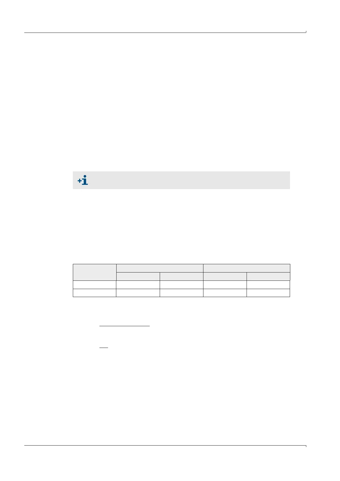
Example:
The sound velocity parameter can be set at “Service” user level (see Service
Manual). It is set to 331.5 m/s at the factory.
Measurement FLOWSIC display Measured value PT100
T in °C T
absolute
in K T in °C T
absolute
in K
1 128 401 115 388
2 186 459 170 443
T
KAL
=CT_1 · T
FLOWSIC
+ CT_0
CT_1 =
CT_0 =
· (T2
PT100
+ T1
PT100
– CT_1 · (T2
FLOWSIC
+ T1
FLOWSIC
))
CT_1 = 0.9483
CT_0 = 7.7310
T2
PT100
– T1
PT100
T2
FLOWSIC
– T1
FLOWSIC
1
2