78 FLOWSIC200 · Operating Instructions · 8013271/1CJ9/V 2-0/2022-01 · © SICK Engineering GmbH
Commissioning and parameterization
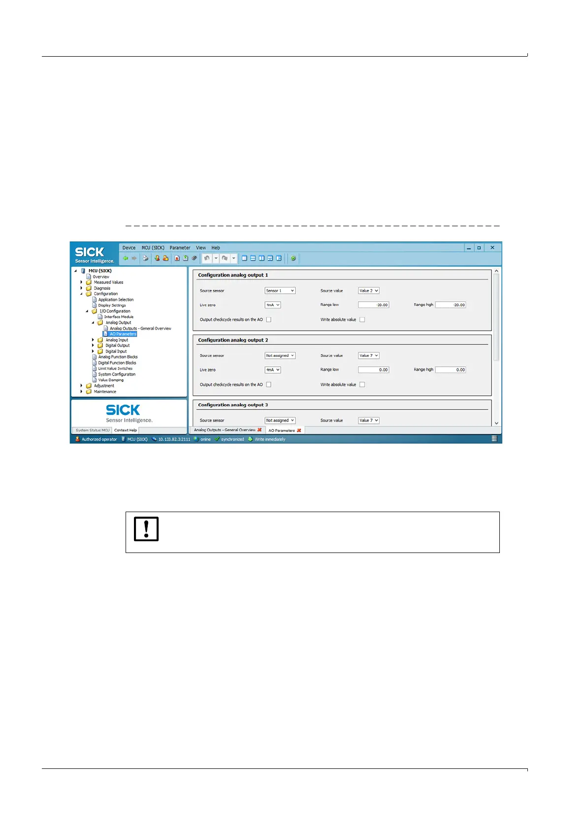
4.2.10 Output flow direction
To output the flow direction, the measuring range must be set in a negative and a positive
range in the “Configuration / I/O Configuration / Analog Output / Analog Outputs” directory.
The zero point then lies between the two end values. Falling below or exceeding the zero
point can additionally be signaled with the limit value relay (
p. 76, §4.2.8).
Example:
Measuring range: -20 ... +20 m/s
The Live zero value (= lower end value) corresponds to a physical value of -20 m/s, the
20 mA value (= upper end value) corresponds to a physical value of +20 m/s.
With Live zero = 4 mA, the zero point is at 12 mA.
Fig. 65 Directory “Configuration / I/O Configuration / Analog Output / Analog Outputs”
Optionally, only the amount of the measured value can be output. For this purpose, the
“Write absolute value” checkbox must be activated.
NOTICE:
The limit value relay must be configured when the absolute value is output,
otherwise no signaling of falling below or exceeding the zero point is possible.