36 FLOWSIC200 · Operating Instructions · 8013271/1CJ9/V 2-0/2022-01 · © SICK Engineering GmbH
Assembly and installation
3.2.2.2
Bus addressing via hardware setting
The bus address of a sender/receiver unit required for the bus system can be assigned by
hardware or software (
p. 93, §4.3.4). Hardware addressing is read in when SOPAS ET
starts (
p. 56, §4.1) and has a higher priority than software addressing.
Bus address and sensor number in the MCU are always identical.
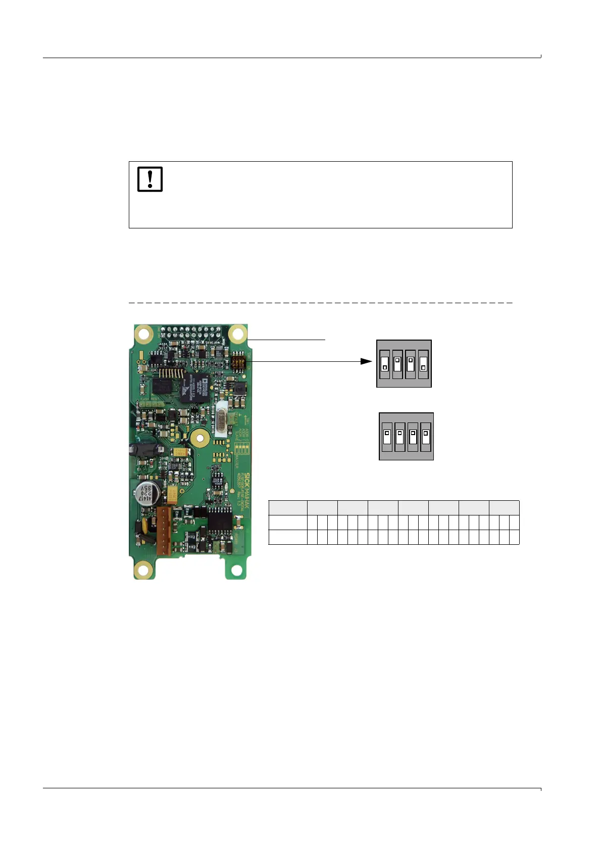
As standard, the address is set using a miniature switch on the digital board in the sender/
receiver unit (3 switches for hexadecimal addressing from address 1 to 7;
Fig. 16). To
change the address, open the sender/receiver unit and set the desired address. Then close
the sender/receiver unit again.
Fig. 16 Hardware addressing of sender/receiver unit
NOTICE:
For bus systems, it must be ensured that the bus addressing of the Master
FLSE200 is set correctly.
The sender/receiver units must have different addresses. Identical addresses
for several units cause the communication with the MCU to abort!
Digital board
Miniature switch
Switch 4 serves for Master -
Slave switch-over
Address 1 2 3 4 5 6 7
Switch 123123123123123123123
ON x x xx xx x xxxxx
Switch
1
2
3
4
Position
OFF
ON
(Switch position for address 1/Master)
1
2
3
4
Position
OFF
ON
1
2
3
4
(No addressing/Slave)