Commissioning and parameterization
FLOWSIC200 · Operating Instructions · 8013271/1CJ9/V2-0/2022-01 · © SICK Engineering GmbH 73
4.2.6 Configuring the analog output
Basic settings
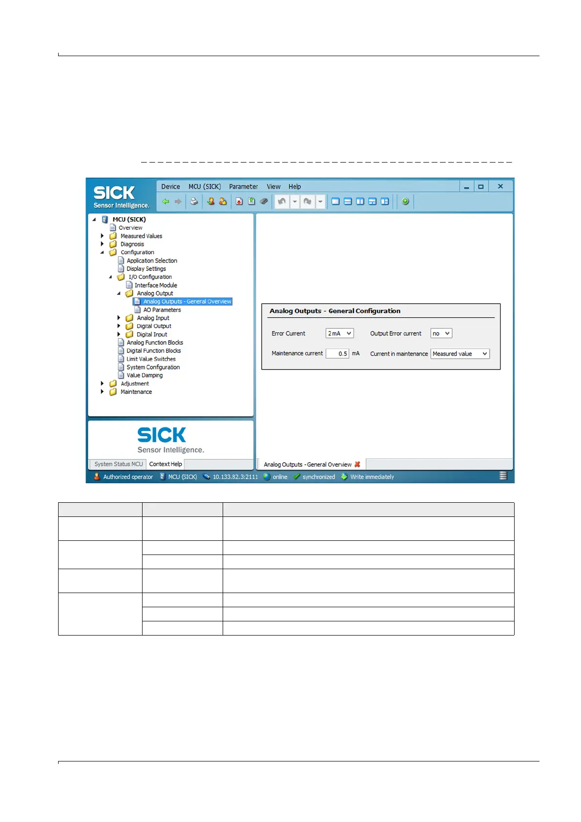
Enter the current to be output on the analog output in the “Maintenance” or “Malfunction”
state in the “Configuration / I/O Configuration / Analog Output / Analog Outputs - General
Overview” directory.
Fig. 60 “Overview” submenu (example for settings)
Field Parameter Remark
Error Current Value < Live Zero (LZ)
or > 20 mA
mA value to be output in “Malfunction” state (error case) (size depends on
connected evaluation system).
Output Error current yes Error current is output.
no Error current is not output.
Maintenance current Value if possible
Live Zero
mA value to be output in “Maintenance” state
Current in
maintenance
User defined value A value to be defined is output during “Maintenance”
Last measured value The value measured last is output during “Maintenance”
Measured value The current measured value is output during “Maintenance”.