40 FLOWSIC200 · Operating Instructions · 8013271/1CJ9/V 2-0/2022-01 · © SICK Engineering GmbH
Assembly and installation
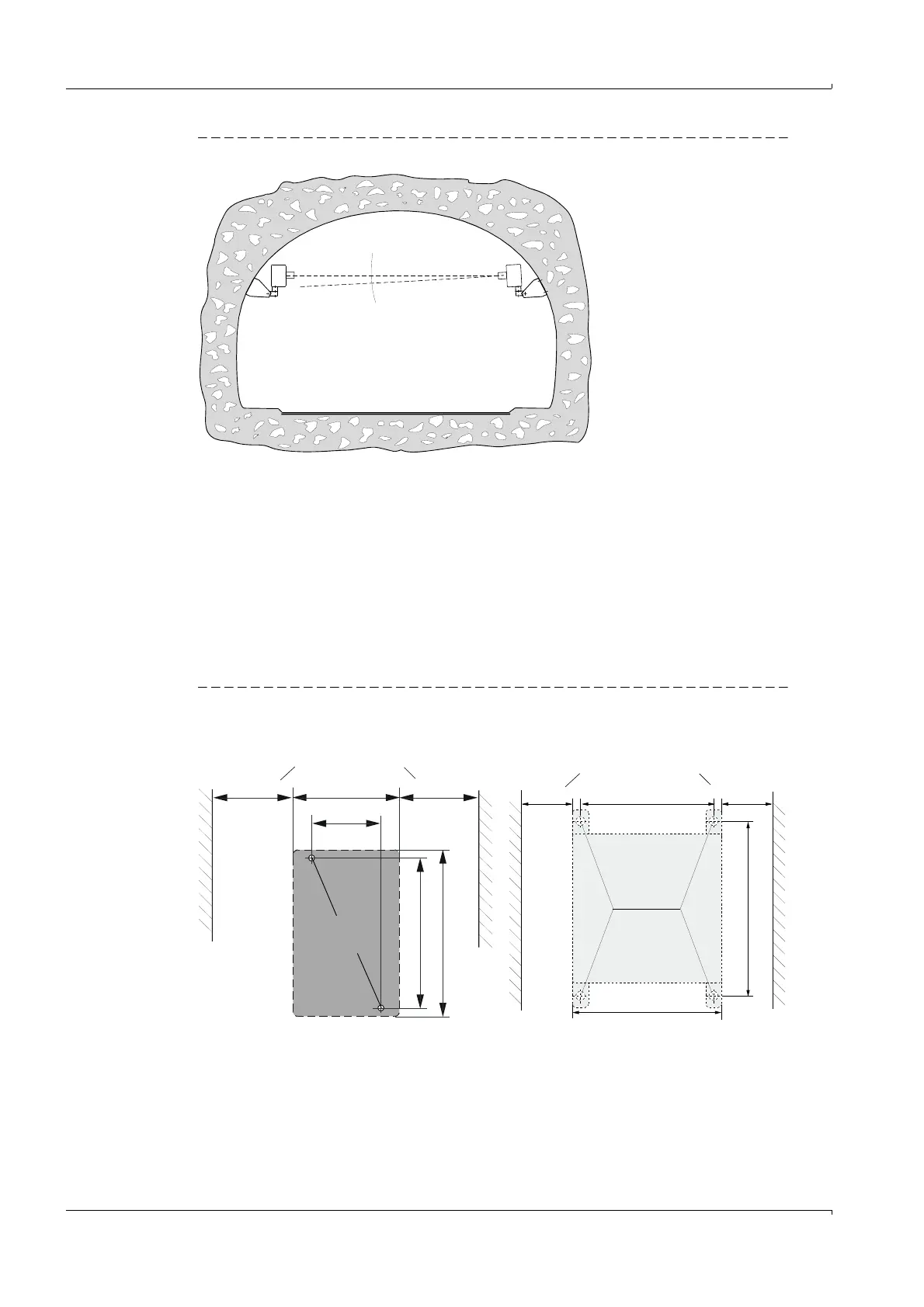
Fig. 23 Permissible horizontal swivel range
In exceptional cases, both sender/receiver units can be installed tilted downwards by up to
5° (
p. 32, §3.1.2).
The sender/receiver units can be aligned in 2 steps:
1 Rough alignment with aid (string or similar) or by sight
2 Fine adjustment with laser pointer or similar.
3.2.5 Installing the junction box
Install this component on a level surface (tunnel wall or roof) as shown in
Fig. 24. For
fastening, the respective suitable mounting kits can be used according to
p. 26, §2.2.5
(drill hole measurements and fitting
p. 34, Fig. 14).
Fig. 24 Junction box installation dimensions
Clearance for cable
> 150
> 150
(80)
52
M4
113
(125)
Clearance for cable
> 150
> 150
(150)
132
176
Aluminium housing Stainless steel housing
M 8