20 FLOWSIC200 · Operating Instructions · 8013271/1CJ9/V 2-0/2022-01 · © SICK Engineering GmbH
Product description
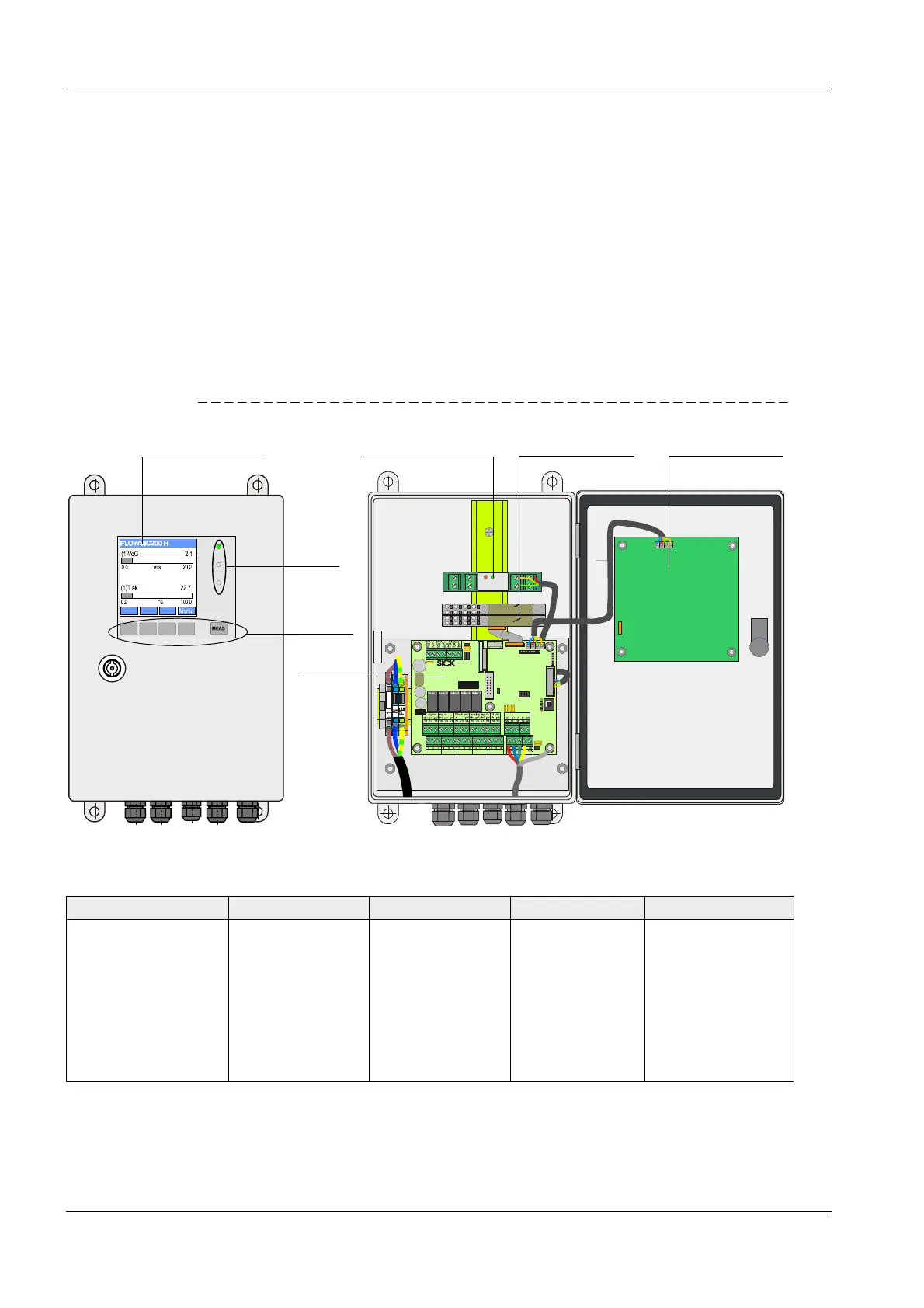
2.2.3 MCU control unit
The control unit has the following functions:
Control of data transfer and processing the data from the sender/receiver units
connected via RS485 interface
Signal output via analog output (measured value) and relay outputs (device status)
Signal input via analog and digital inputs
Voltage supply for the connected sender/receiver units
Communication with host control systems via optional modules
System and device parameters can be set easily and conveniently via a USB interface
using a laptop and the user-friendly SOPAS ET operating software. The parameters are
stored reliably even in the case of a power failure.
The control unit is usually installed in a stainless steel housing.
Fig. 7 MCU control unit options
Standard interfaces
DISPLAYMODUL
relay 3 relay 4 relay 5
BUS - S/E unit 1
BUS
Ter m
Ter m
BUS - S/E unit 2
relay 1
relay 2
com nc. no. com nc. no. com nc. no. com nc. no. com nc. no.
Reset
LED
Control
buttons
Processor
board
Option Display module Option Interface module Options I/O module Option Display module
Analog output Analog inputs Relay outputs Digital inputs Communication
1 output 0/2/4...22 mA
(electrically isolated,
active); for selectable
output of measured
variables:
–Velocity
–Air temperature
Resolution 0.01 mA
2 inputs 0 ... 20 mA
(Standard; without
electric isolation)
Resolution 0.01 mA
5 NC contacts (48 V,
1 A) to output status
signals:
– Operation/
malfunction
– Maintenance
– Check cycle
– Maintenance
request
– Limit value/direction
2 inputs to connect
potential-free
contacts for a
maintenance switch or
triggering a check
cycle
– USB 1.1 and RS232
(on terminals) for
measured value
inquiries, setting
parameters and
software updates
– RS485 for sensor
connection