Product description
FLOWSIC200 · Operating Instructions · 8013271/1CJ9/V2-0/2022-01 · © SICK Engineering GmbH 21
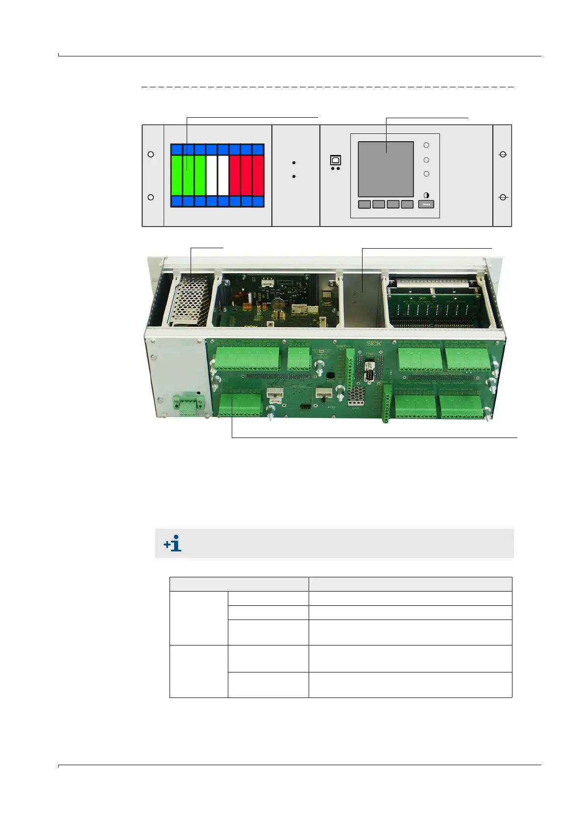
Fig. 8 MCU control unit in 19" housing with options
Options
The options described in the following can considerably expand the functionality of the
MCU:
1 Display module
Module to display measured values and status information of the connected sender/
receiver unit(s) using control buttons (capacitive sensors).
–Displays
REQUEST
INTERFACE-MODULE
I/O-MODULE
POWER
ERROR
TxD RxD
Plug-in slots for optional I/O modules Display module option
Backplane with terminal connections for wiring by customer
Power supply slot for Interface module option
The integration of this module into already delivered control units can only
be done by the supplier.
Type Display
LED
Power (green) Voltage supply OK
Failure (red) Function fault
Maintenance
request (yellow)
Maintenance request
LC display
Graphic display
(main display)
– Flow velocity
–Air temperature
Text display
2 measured values (see graphic display) and 6
diagnosis values