22 FLOWSIC200 · Operating Instructions · 8013271/1CJ9/V 2-0/2022-01 · © SICK Engineering GmbH
Product description
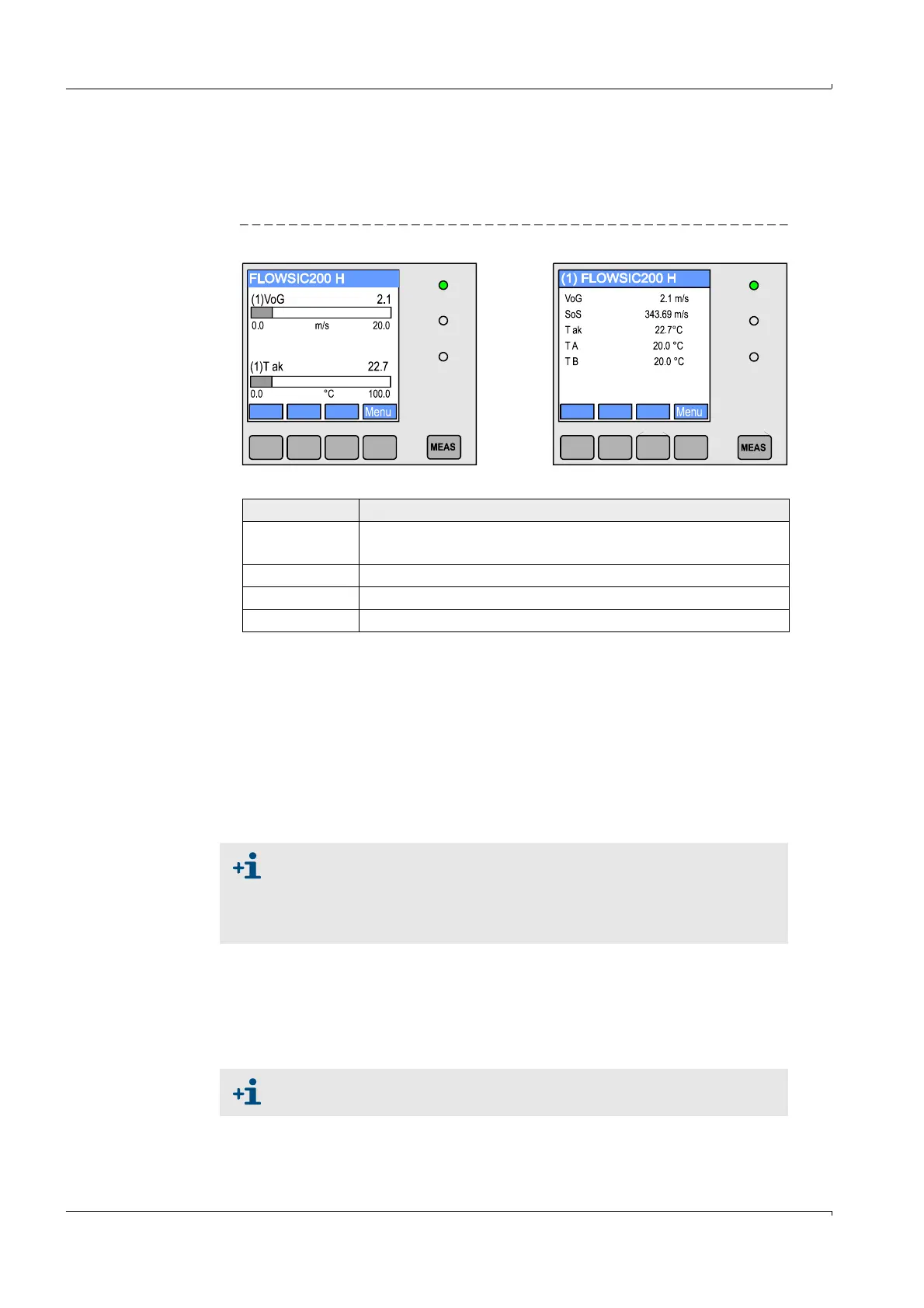
In the graphic display, two factory-preselected main measured values of a
connected sensor pair are shown in a bar graph. Alternatively, up to 8 single
measured values of a sender/receiver unit can be displayed (toggle with “Meas”
button).
Fig. 9 LC display with graphic (left) and text (right) display
– Control buttons
2 I/O module
For plugging onto module carrier (MCU in wall-mounted housing) or in slide-in module
(MCU in 19" housing), optionally as:
– Analog output module with 2 outputs 0/4 ... 22 mA to output further measured
variables (load 500 )
– Analog input module with 2 inputs 0/4 ... 22 mA to read in values from external
sensors
– Digital output module with 2 outputs (NC contact, contact load 48 V AC/DC, 5 A)
– Digital output module with 4 outputs (NO contact, contact load 48 V AC/DC, 0,5 A)
3 Interface module
Module to pass on measured values, system status and service information to higher
level control systems, optionally for Profibus DP V0, Ethernet or MODBUS, to plug onto a
hat rail (MCU in a wall housing) or slot (MCU in 19" housing). The module is connected
to the connection board with an associated cable.
Button Function
Meas
– Toggles between text and graphic display
– Displays the contrast settings (after 2.5 s)
Arrows Selects next/previous measured value screen
Status Displays alarm or error messages
Menu Displays main menu and selection of submenus
One module carrier is required per module (to plug in on the hat rail).
One module carrier has to be connected to the processor board with a
special cable, other module carriers can be docked to it.
A maximum of 8 I/O modules can be plugged in, of which a maximum of
4 modules of the same type.
Profibus DP-V0 for transfer via RS485 according to DIN 19245 Part 3 as
well as IEC 61158.