Assembly and installation
FLOWSIC200 · Operating Instructions · 8013271/1CJ9/V2-0/2022-01 · © SICK Engineering GmbH 51
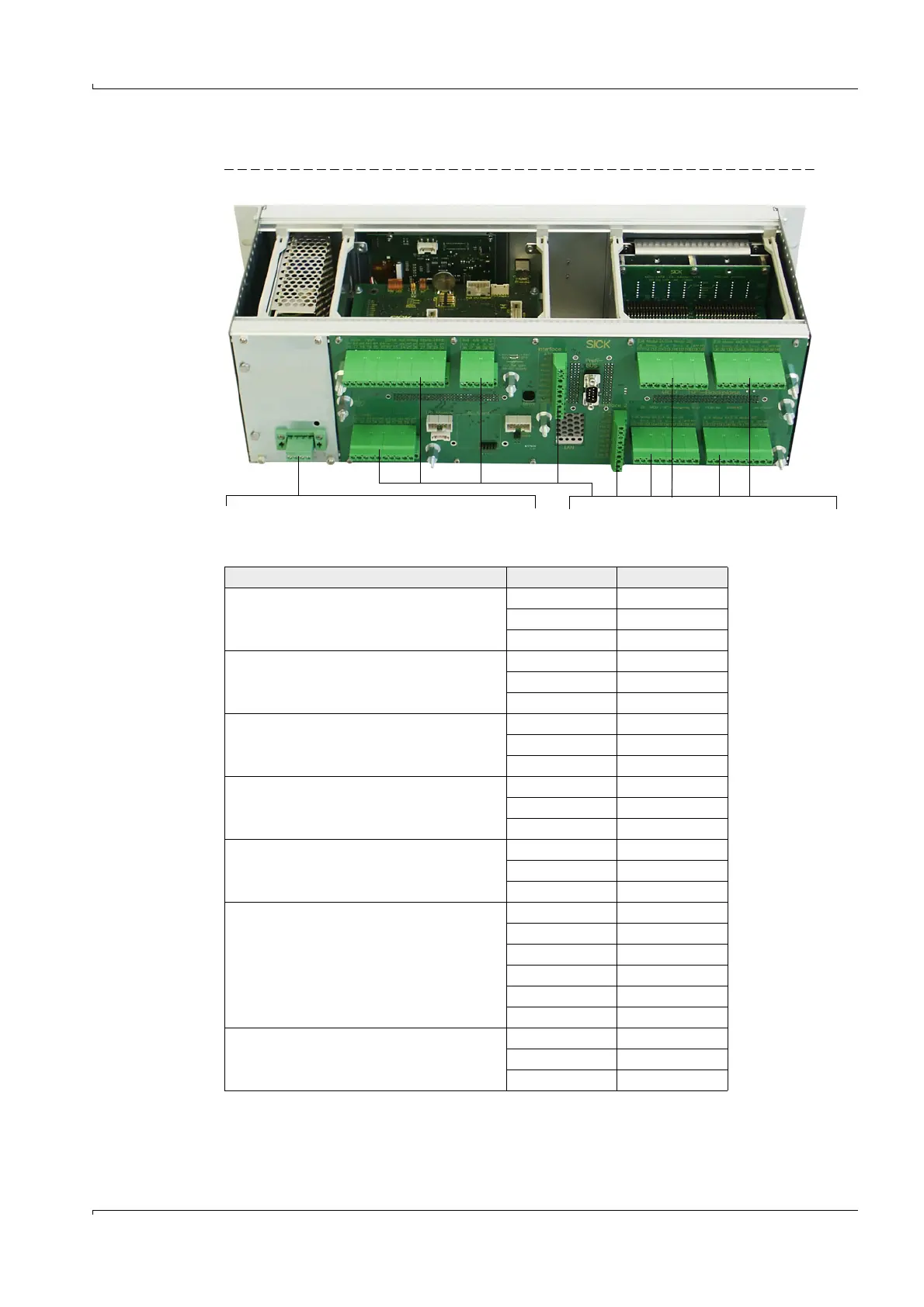
3.3.5 Connecting the control unit in the 19" housing
Fig. 34 Connections for MCU 19” variant
1)
Fuse ratings, see type plate or identification plate on fuse holder.
Terminal connection for power supply 90 ... 250 V AC
1)
Terminal connection for customer wiring
Function Connection Terminal No.
Output relay 1 (operation/malfunction) com 1
n.c.
1)
2
n.o.
2)
3
Output relay 2 (maintenance) com 4
n.c.
1)
5
n.o.
2)
6
Output relay 3 (check cycle) com 7
n.c.
1)
8
n.o.
2)
9
Output relay 4 (maintenance request) com 10
n.c.
1)
11
n.o.
2)
12
Output relay 5 (limit value) com 13
n.c.
1)
14
n.o.
2)
15
Digital input d in 1 16
d in 2 17
gnd 18
d in 3 19
d in 4 20
gnd 21
Analog output + 22
-23
gnd 24