50 FLOWSIC200 · Operating Instructions · 8013271/1CJ9/V 2-0/2022-01 · © SICK Engineering GmbH
Assembly and installation
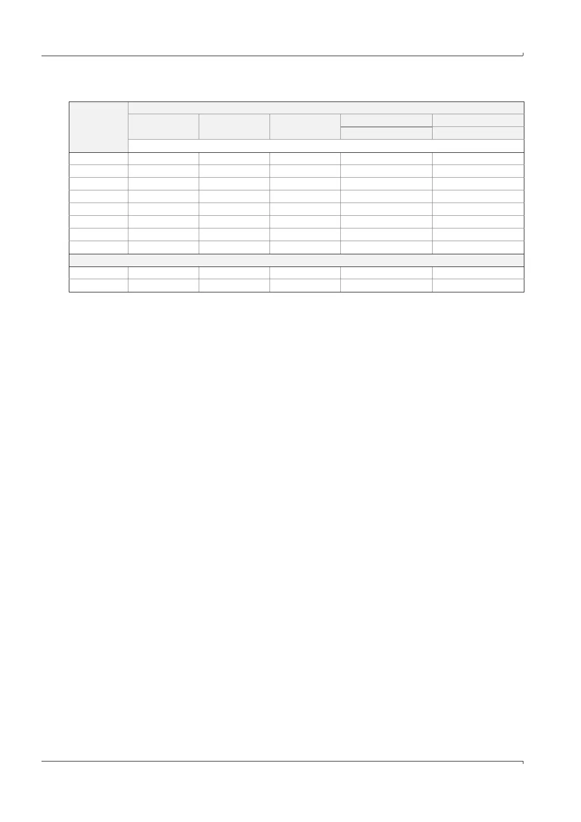
Connection data
n.c.: normal closed
n.o.: normal open
Connection Module type
2x analog
input
2x analog
output
2x digital
input
Digital output Digital output
2 NC contacts 4 NO contacts
Assignment
11 AI 1+ AO 1+ DI 1+ n.c. relay 1 n.o. relay 1
12 AI 1- AO 1- gnd com. relay 1 com. relay 1
13 AI 2- AO 2- gnd com. relay 2 com. relay 3
14 Screen (gnd) Screen (gnd) DI 3+ n.c. relay 2 n.o. relay 3
21 AI 2+ AO 2+ DI 2+ n.o. relay 1 n.o. relay 2
22 AI 1- AO 1- gnd com. relay 1 com. relay 2
23 AI 2- AO 2- gnd com. relay 2 com. relay 4
24 Screen (gnd) Screen (gnd) DI 4+ n.o. relay 2 n.o. relay 4
Load
Max. voltage 3 V d.c. 15 V d.c. 5.5 V d.c. 30 V a.c./d.c. 24 V DV
Max. current 22 mA 22 mA 5 mA 2 A 36 mA