Assembly and installation
FLOWSIC200 · Operating Instructions · 8013271/1CJ9/V2-0/2022-01 · © SICK Engineering GmbH 49
Fitting and connecting optional Interface and I/O modules
Plug Interface modules and module carriers for I/O modules onto the hat rail in the MCU
(
p. 46, Fig. 27) and connect to the associated connection on the processor board with the
cable with plug-in connector (
p. 47, Fig. 28). Then plug the I/O modules on the module
carriers.
Connect the I/O modules to the terminal points on the module rack (
Fig. 30, Fig.31,
Fig.32), the Profibus module to the module terminals and the Ethernet module using on-site
network cables.
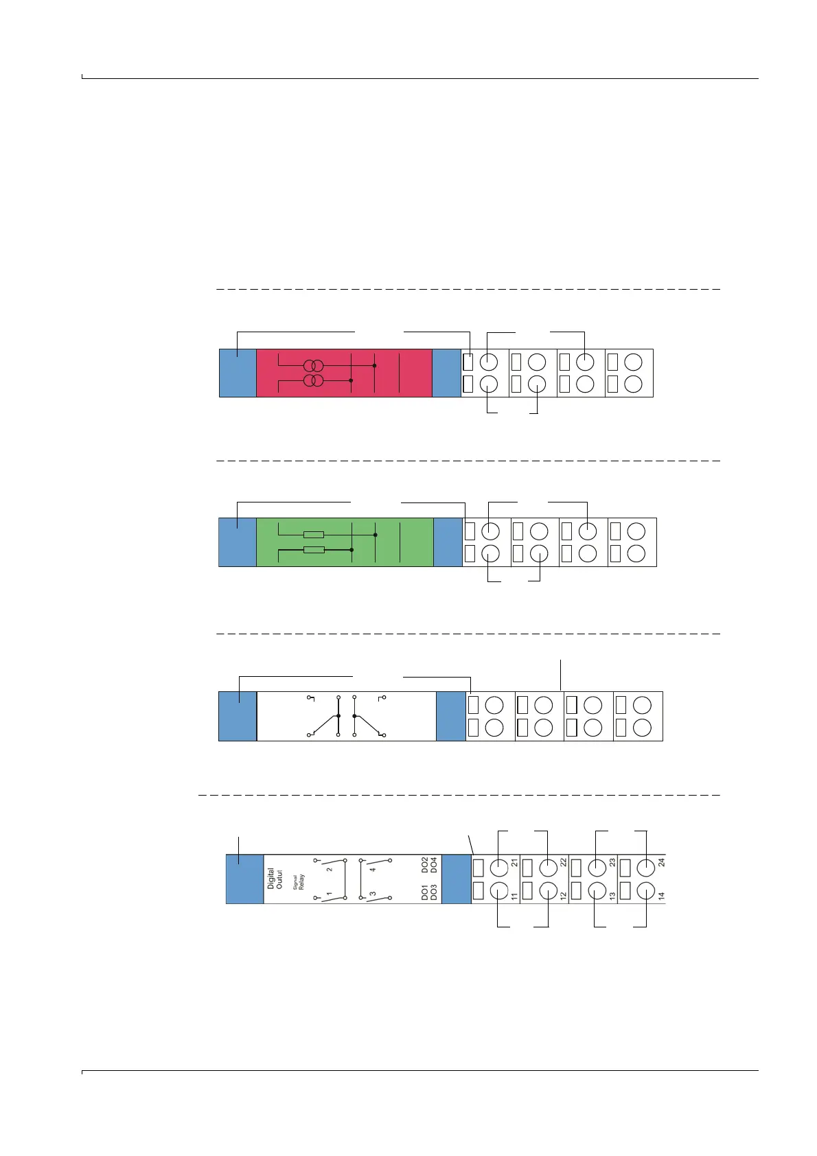
AO module terminal assignment
Fig. 30 Analog output module terminal assignment
AI module terminal assignment
Fig. 31 Analog input module terminal assignment
DO module terminal assignment (2 NC contacts)
Fig. 32 Digital output module terminal assignment
DO module terminal assignment (4 NO contacts)
Fig. 33 DO module terminal assignment (4 NO contacts)
+
1
AO1
+
2
AO2
Shield
11
12
13
14
21
22
23
24
+-
Analog output module Module carrier
AO 1
+-
AO 2
+
1
AI1
11
12
13
14
21
22
23
24
+
2
AI2
Shield
Analog input module Module carrier
+-
AI 2
+-
AI 1
Digital
Outut
1
2
DO1
DO2
Power
Relay
11
12
13
14
21
22
23
24
DO1 DO2
n.o. com. com. n.o.
Digital output module Module carrier
n.o. com. com. n.o.
DO1 DO3
Digital output module Module carrier
DO2 DO4
n.o. com. com. n.o.