106 FLOWSIC200 · Operating Instructions · 8013271/1CJ9/V2-0/2022-01 · © SICK Engineering GmbH
Malfunctions
6.1
General information
Warnings or device malfunctions are output as follows:
On the MCU, the respective relay is switched on (
p. 48, Fig. 29).
“Maintenance requ.” or “Failure” is displayed in the status bar of the MCU LC display
(
p. 95, §4.4.1). The respective LED (“MAINTENANCE REQUEST” for warning, “FAILURE”
for malfunction) also goes on.
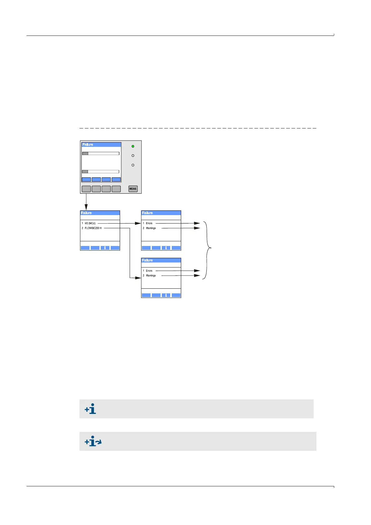
After pressing the button “Diag”, possible causes are shown as short information in the
menu “Diagnosis” after selecting the device (“MCU” or ”FLOWSIC200 H”).
Fig. 92 Display on the LC display
Detailed information on the current device status is provided by the “Diagnosis / Error
messages / Warnings” directories. For display, connect the measuring system to SOPAS ET
and start the device file “FLOWSIC200 M/FLOWSIC200 H/FLOWSIC200 H-M” or “MCU”
(
p. 58, §4.1.3 and
p. 64, §4.1.4).
Move the mouse pointer to the respective message to display more details on the
significance of individual messages in a separate window. Clicking on the display shows a
short description of possible causes and corrections under “Help” (
p. 108, Fig. 93,
p. 109, Fig. 94).
Warning messages are output when internal limits for individual device functions/
components are reached or exceeded which can then lead to erroneous measured values
or an imminent failure of the measuring system.
Diagnosis I/O Diagnosis
Diagnosis
/diag /i/o/status
/sensor/1/status
Back Enter Back Enter
Back Enter
Menu
(1)VoG
1.04
0.0 m/s 100.0
0.0 m/s 500.0
(1)SoS
334.21
Display of current warning or failure
Warning messages do not imply a malfunction of the measuring system. The
current measured value continues to be output on the analog output.
See the Service Manual for a detailed description of messages and options for
clearance.