Product description
FLOWSIC200 · Operating Instructions · 8013271/1CJ9/V2-0/2022-01 · © SICK Engineering GmbH 15
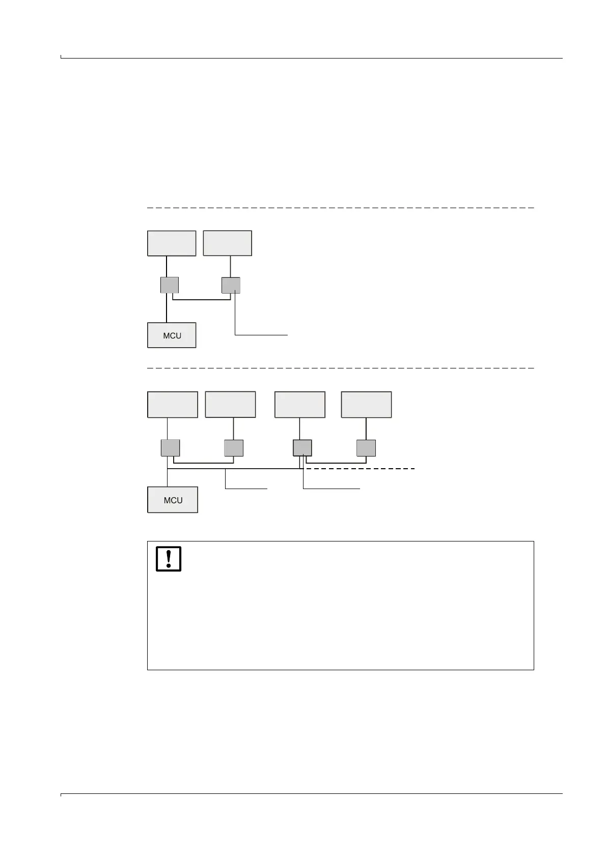
2.1.2 Communication between sender/receiver units and control unit
Standard version
The two sender/receiver units (FLSE) work as Master and Slave. The master FLSE has a
second interface to be able to completely separate communication to the slave FLSE and to
the MCU. The master triggers the slave and controls measurement. The MCU can request
measured values from the master unit independent of the measuring cycle (asynchronous).
For wiring, the junction box is installed on both FLSEs. Interface division runs in the master
FLSE junction box.
Fig. 2 Bus connection FLSE200 - MCU with one measuring point
Fig. 3 Bus connection FLSE200 - MCU with several measuring points
With the bus version, up to eight sensors can be connected to one MCU.
FLSE200
Master
FLSE200
Slave
FLSE200
Master
FLSE200
Slave
FLSE200
Slave
FLSE200
Master
NOTICE:
For bus wiring, the factory-set termination must be disabled in the system
components not at the end of the line.
To ensure the power supply for all connected measuring points, follow the
instructions on
p. 45, §3.3.2.2.
The S/R units of the FLOWSIC200 must be set to address 1 ... 7 on the
hardware side (
p. 36, §3.2.2.2).
The physical order of the sensors on the bus does not necessarily have to
match the logical address assignment, it is just not allowed to assign
addresses twice.