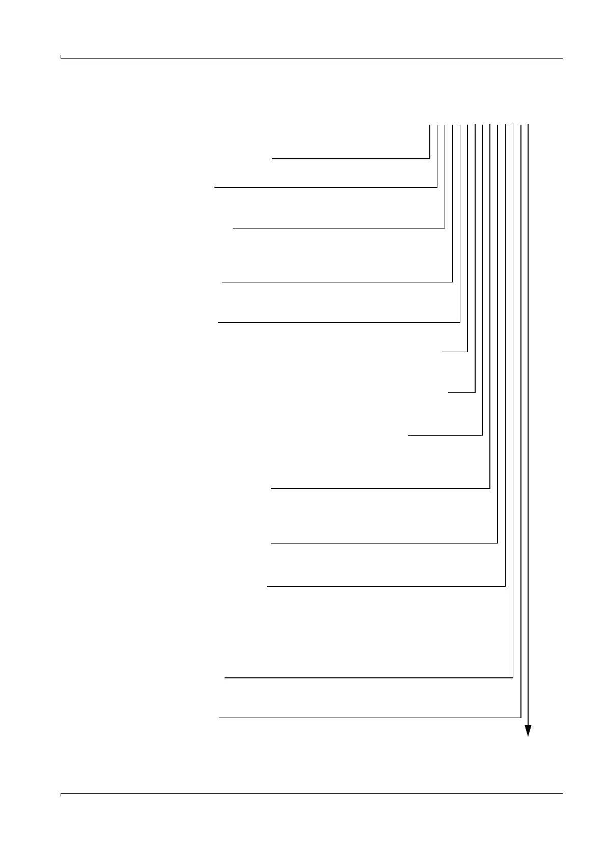
Type code - control unit: Control unit type code: MCU-X
X X X X X X X X X X X X X
Integrated purge air supply
- N: Without blower
Power supply
- W: 90 ... 250 V AC
- 2: Optional 24 V DC
Housing variants
- S: Wall-mounted housing, painted, gray stainless steel 1.4571
or equivalent
- R: 19” housing, terminal connection
Display module
- N: Without (only variant in wall-mounted housing)
- D: With
Other options
- N: Without
Optional analog input (plug-in module; 0/4...20 mA; 2 per module)
- 0: Without
- n: With, n = 1, 2
1)
Optional analog output (plug-in module; 0/4...20 mA; 2 per module)
- 0: Without
- n: With, n = 1...2
1)
Optional digital input (plug-in module; 4 inputs per module)
- 0: Without
- n: Number on request
Option - digital output power (plug-in module; 48 V DC, 5 A;
2 NC contacts per module)
- 0: Without
- n: Number on request
Option - digital output low power (plug-in module; 48 V DC, 0.5 A;
4 NO contacts per module)
- 0: Without
- n: Number on request
Optional Interface module
- N: Without Interface module
- B: T/P-MOD Ethernet V1,COLA-B, pulse 2)
- V: T/P-MOD Ethernet V1,COLA-B, 3-fold, pulse 2)
- Q: T/P-MOD Ethernet V2, MODBUS TCP, pulse 2)
- D: T/P-MOD RS485,MODBUS ASCII/RTU, pulse 2)
- F: T/P-MOD RS485, PROFIBUS, pulse 2)
Special features
- N: Without special version
- S: Special solution
EX certification
- N: Without EX certification