74 FLOWSIC200 · Operating Instructions · 8013271/1CJ9/V 2-0/2022-01 · © SICK Engineering GmbH
Commissioning and parameterization
Configuration
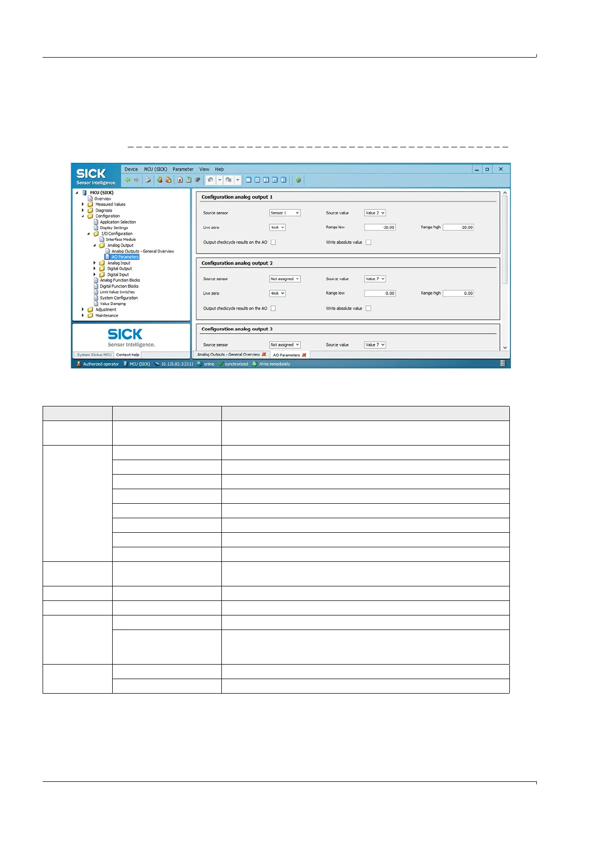
In directory “Configuration / I/O Configuration / Analog Output / Analog Outputs”, the
signal source (measuring signal of a sender/receiver unit) can be assigned to the standard
analog output (AO) and live zero and measuring range can also be defined.
Fig. 61 “AO Parameters” subdirectory (example for settings)
* Not relevant for FLOWSIC200
Field Parameter Remark
Source sensor Sensor 1 to 8 Sender/receiver unit whose output signal is to be assigned to the analog
output.
Source value Measured value 1 Volume flow in operating conditions*
Measured value 2 Flow velocity
Measured value 3 Sound velocity
Measured value 4 Acoustic temperature
Measured value 5 Temperature A*
Measured value 6 Temperature B*
Measured value 7 Signal to noise ratio A
Measured value 8 Signal to noise ratio B
Live zero Zero point (0, 2 or 4 mA) Select 2 or 4 mA to differentiate clearly between measured value and device
switched off, or current loop interrupted.
Range low Lower measuring range limit Physical value at live zero
Range high Upper measuring range limit Physical value at 20 mA
Output check
cycle results on
the AO
Inactive Control values (
p. 28, §2.4) are not output on the analog output.
Active Control values are output on the analog output (the “Output control values at
AO” checkbox in the “Adjustment / Function Check - Automatic” directory must
be activated).
Write absolute
value
Inactive Positive and negative measured values are differentiated.
Active The amount of the measured value is output.