18 FLOWSIC500 · Operating Instructions · 8025733/1GMJ/V4-2/2022-07 · © SICK Engineering GmbH
Product description
Subject to change without notice
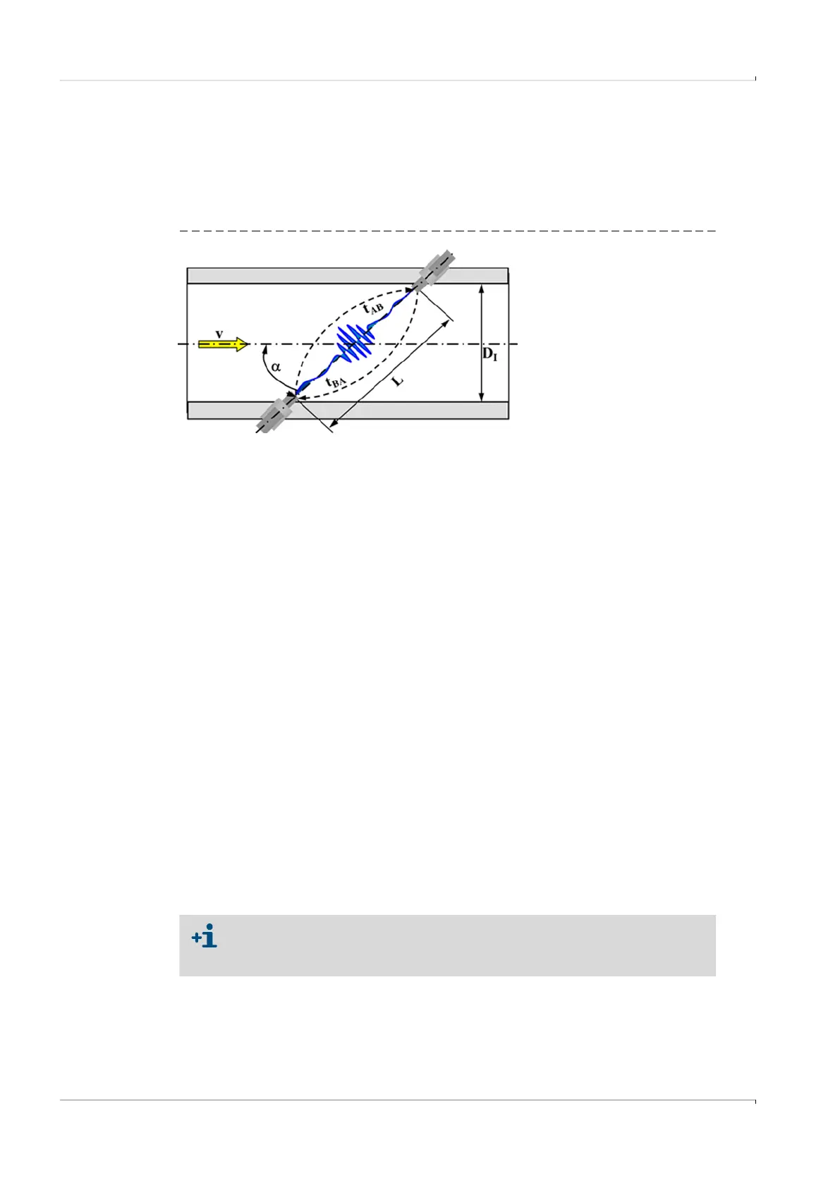
2.1 Measuring principle
2.1.1 Gas flow meter
The FLOWSIC500 works according to the principle of ultrasonic transit time difference
measurement.
Fig. 2 Functional principle
Measured signal transit times t
AB
and t
BA
are defined by the current sound and gas velocity.
Gas velocity v is determined from the difference between the signal transit times. Therefore
changes in the sound velocity caused by pressure or temperature fluctuations do not affect
the calculated gas velocity with this measurement method.
The FLOWSIC500 calculates the volume flow rate internally from the gas velocity and the
diameter of the measuring section of the gas flow meter.
2.1.2 Volume conversion (optional)
The integrated volume conversion converts the measured gas volume from measurement
conditions to base conditions.
Calculation according to EN 12405:
The measurement conditions are either determined with pressure and temperature
sensors or entered as fixed value.
v = Gas velocity
L = Measuring path
= Angle of inclination in °
t
AB
= Sound transit time
in flow direction
t
BA
= Sound transit time
against flow direction
D
I
= Pipe inner diameter
Q = Volume flow
The following short forms are used in this document for better readability:
● Volume at base conditions = base volume
● Volume at flowing conditions = measurement volume
Q
4
---
D
I
2
L
2 cos
----------------
t
BA
t
AB
–
t
AB
t
BA
----------------------
=
V
b
C V
m
=
V
b
= Volume at base conditions
C = Conversion factor
V
m
= Volume at measurement conditions
p = Gas pressure at measurement conditions
p
b
= Pressure at base conditions
T = Gas temperature at measurement conditions
T
b
= Temperature at base conditions
Z
b
= Compression factor at base conditions
Z = Compression factor at measurement conditions
C
p
p
b
-----
T
b
T
------
Z
b
Z
------
=