Installation
FLOWSIC500 · Operating Instructions · 8025733/1GMJ/V4-2/2022-07 · © SICK Engineering GmbH 55
Subject to change without notice
3.4.8 Cable specifications
When the plugs available from SICK are used, a shielded control cable with 4x0.25 mm
2
cross-section, with PVC insulation and approx. 5 mm outer diameter is required.
SICK recommends the ready-made cables available as accessories (→ p. 136, §8.1).
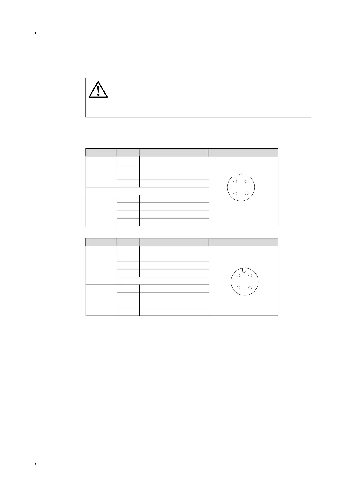
Wire colors of the cable available as spare part
Table 18 Power supply cable; for connection to plug-in connector 1, B-coded
Table 19 Data cable for connection to plug-in connector 2, A-coded
WARNING: Requirements on cables and installation
▸
Pay attention to the requirements in EN 60079-14 when selecting the
cables and during installation!
▸
Further legal requirements must be observed for use in explosive
atmospheres.
Part No. Pin Wire color Plug
2067424,
2067425
1 Brown
2 White
3 Blue
4 Black (or yellow/green)
2067632,
2067633
1 White
2 Brown
3 Green
4 Yellow
Part No. Pin Wire color Plug
2067422,
2067423
1 Brown
2 White
3 Blue
4 Black (or yellow/green)
2067630,
2067631
1 White
2 Brown
3 Green
4 Yellow